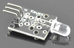
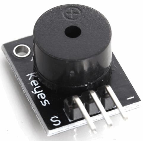
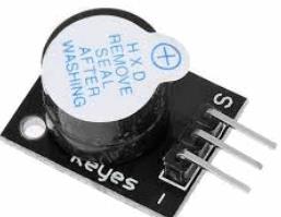
http://sites.schaltungen.at/arduino-uno-r3/starter-kit-lern-set/37-in-1-sensor/arduinosensors
http://www.linksammlung.info/
http://www.schaltungen.at/
Wels, am 2017-01-11
BITTE nützen Sie doch rechts OBEN das Suchfeld [ ] [ Diese Site durchsuchen]
DIN A3 oder DIN A4 quer ausdrucken
**********************************************************************************
DIN A4 ausdrucken
*********************************************************
|
704_d_#16-11s46-x_160152-11 Sensoren (1) 37-in-1 - Digital 30_1a.pdf
|
|
704_d_#16-12s33-x_160173-11 Sensoren (2) 37-in-1 – Analog-Digital 7_1a.pdf
|
|
704_d_#17-01s74-x_160173-11 Sensoren (3) 37-in-1 - OneWire RC5-Protok._1a.pdf
|
|
704_d_#14-07s32-x_140009-11 Elektor Extension-Shield für Sensoren (0) 37-in-1_1a.pdf
|
|
704_d_ARDUINO-x_37-in-1 box Sensor Kit For Arduino Starters - SunFounder Datasheet (67 Seiten)_1a.pdf
|
|
715_d_ARDUINO-x_37-in-1 Sensor kit for Arduino +++ Beschreibung (51 Seiten)_1a.pdf
|
|
715_d_ARDUINO-x_37-in-1 Sensor kit For Arduino +++ MANUAL (83 Seiten)_1a.pdf
|
|
715_d_ARDUINO-x_37-in-1 Sensor Kit for ARDUINO - Pin-Belegung (12 Seiten)_1a.pdf
|
|
715_d_ARDUINO-x_ALLNET Arduino 37-in-1 Sensor Kit +++ Beschreibung (12 Seiten)_1a.pdf
|
|
715_d_ARDUINO-x_ALLNET Arduino 37-in-1 Sensor Kit - Experimentierkasten (7 Seiten)_1a.pdf
|
|
715_d_ARDUINO-x_jOY-iT Arduino 37-in-1 Sensor Kit +++ Kurz-Beschreibung (12 Seiten)_1a.pdf
|
|
715_d_ARDUINO-x_jOY-iT Arduino 37-in-1 Sensor Kit X40 +++ Beschreibung (227 Seiten)_1a.pdf
|
|
~715_d_ARDUINO-x_37-in-1 Sensor Kit for ARDUINO - First acquaintance (42 Seiten)_1a.pdf
|
|
~715_d_ARDUINO-x_37-in-1 Sensor Kit for ARDUINO - Spanisch (51 Seiten)_1a.pdf
|
|
704_d_ARDUINO-x_37-in-1 box Sensor kit for ARDUINO Starters - MANUAL (67 Seiten)_1a.pdf
|
|
715_d_ARDUINO-x_150001-11 Arduino 37-in-1 Sensor kit - Kurzbeschreibung (7 Seiten)_1a.pdf
|
|
715_d_ARDUINO-x_150001-91 Arduino 37-in-1 Sensor kit - ALLNET deutsch (7 Seiten)_1a.pdf
|
|
715_d_ARDUINO-x_150001-91 Arduino 37-in-1 Sensor kit - Elektor Information (7 Seiten)_1a.pdf
|
|
715_d_ARDUINO-x_37-in-1 Sensor kit for ARDUINO +++ Anleitung (77 Seiten)_1a.pdf
|
|
715_d_ARDUINO-x_37-in-1 Sensor kit for ARDUINO - SKA-36 (6 Seiten)_1a.pdf
|
1. ArduinoSensors for microcontrollers
http://arduinosensors.nl/
http://arduinosensors.nl/index.php?route=product/product&path=25_29&product_id=92
Arduino 37-in-1 Sensor kit Documentation (Download) € 0,53
Documentation about the 37 in one sensor kit. Contains codes for each sensor from the kit..
http://arduinosensors.nl/index.php?route=product/category&path=17
http://arduinosensors.nl/index.php?route=account/login
[email protected]
f***z++A
ArduinoSensors 37-in-1 Sensorkit Documentation € 0,55 gekauft download
ORDNER > ArduinoSensors > Arduino Sensors.nl CODES-Sketches.zip
|
Arduino KY-001 Temperature sensor module - TkkrLab.pdf
|
|
Arduino KY-002 Vibration switch module - TkkrLab.pdf
|
|
Arduino KY-003 Hall magnetic sensor module - TkkrLab.pdf
|
|
Arduino KY-004 Key switch module - TkkrLab.pdf
|
|
Arduino KY-005 Infrared emission sensor module - TkkrLab.pdf
|
|
Arduino KY-006 Small passive buzzer module - TkkrLab.pdf
|
|
Arduino KY-008 Laser sensor module - TkkrLab.pdf
|
|
Arduino KY-009 3-color full-color LED SMD modules - TkkrLab.pdf
|
|
Arduino KY-009 3-color full-color LED SMD modules - TkkrLab.pdf.lnk
|
|
Arduino KY-010 Optical broken module - TkkrLab.pdf
|
|
Arduino KY-011 2-color LED module - TkkrLab.pdf
|
|
Arduino KY-012 Active buzzer module - TkkrLab.pdf
|
|
Arduino KY-013 Temperature sensor module - TkkrLab.pdf
|
|
Arduino KY-015 Temperature and humidity sensor module - TkkrLab.pdf
|
|
Arduino KY-016 3-color LED module - TkkrLab.pdf
|
|
Arduino KY-017 Mercury open optical module - TkkrLab.pdf
|
|
Arduino KY-018 Photo resistor module - TkkrLab.pdf
|
|
Arduino KY-019 5V relay module - TkkrLab.pdf
|
|
Arduino KY-020 Tilt switch module - TkkrLab.pdf
|
|
Arduino KY-021 Mini magnetic reed modules - TkkrLab.pdf
|
|
Arduino KY-022 Infrared sensor receiver module - TkkrLab.pdf
|
|
Arduino KY-023 XY-axis joystick module - TkkrLab.pdf
|
|
Arduino KY-024 Linear magnetic Hall sensors - TkkrLab.pdf
|
|
Arduino KY-025 Reed module - TkkrLab.pdf
|
|
Arduino KY-026 Flame sensor module - TkkrLab.pdf
|
|
Arduino KY-027 Magic light cup module - TkkrLab.pdf
|
|
Arduino KY-028 Temperature sensor module - TkkrLab.pdf
|
|
Arduino KY-029 Yin Yi 2-color LED module 3MM - TkkrLab.pdf
|
|
Arduino KY-031 Sensor module - TkkrLab.pdf
|
|
Arduino KY-032 Obstacle avoidance sensor module - TkkrLab.pdf
|
|
Arduino KY-033 Hunt sensor module - TkkrLab.pdf
|
|
Arduino KY-034 Automatic flashing colorful LED module - TkkrLab.pdf
|
|
Arduino KY-035 Class Bihor magnetic sensor - TkkrLab.pdf
|
|
Arduino KY-036 Metal touch sensor module - TkkrLab.pdf
|
|
Arduino KY-037 Sensitive microphone sensor module - TkkrLab.pdf
|
|
Arduino KY-038 Microphone sound sensor module - TkkrLab.pdf
|
|
Arduino KY-039 Detect the heartbeat module - TkkrLab.pdf
|
|
Arduino KY-040 Rotary encoder module - TkkrLab.pdf
|
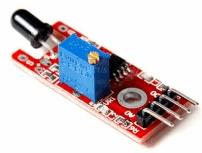
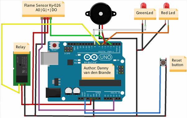
1.01 KY-026 Flame - Flammen-Sensor § Modul=pin-4 & pin-A0 Buzzer=pin-3 LEDgrün=pin-8 LEDrot=pin-6 Taster=pin-Reset Relais=pin-7
1.02 KY-013 NTC Temperatur-Sensor § NTC=pin-A0 LCD1602=pin-16, 17
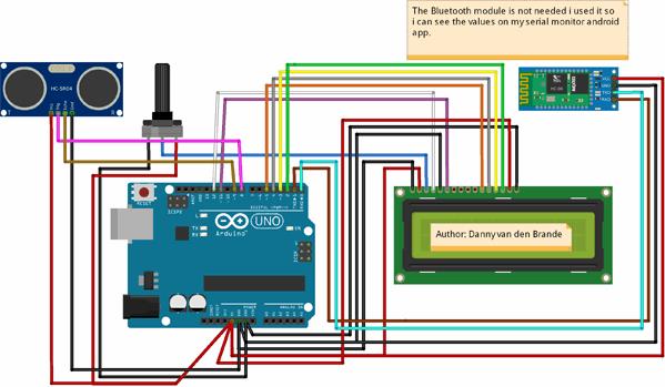
1.03 KY-050 Ultrasonic - Distanzsensor § HC-SR04=pin-8, 9 LCD1602=pin-2..5
1.04 KY-034 7-color flash - 7-Farben LED-Modul § LED=pin-13
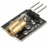
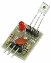
1.05 KY-008 Laser emitter - Laser-Transmitter Modul § Emitter=pin-6 Detector=pin-7 Buzzer=pin-8 7-color-LED=pin-4 Relais=pin-5
1.06 KY-999 Laser receiver - Laserempfänger mit LED § Sender=pin-6 Receiver=pin-7 Buzzer=pin-8 7-color-LED=pin-4 Relais=pin-5
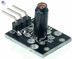
1.07 KY-002 Shock - Vibrations-Sensor - Schwingungs-Sensor § Modul=pin-6 RGB-LED=pin-4, 5 Buzzer=pin-7
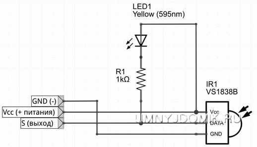
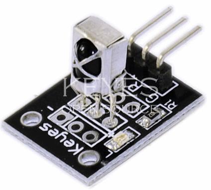
1.08 KY-022 IR receiver - Infrarot-Empfänger § IR-Transistor=pin-4 RGB=pin-6, 7, 8 Buzzer=pin-9 4xRelais=pin-5 pin-10, 11, 12
1.09 KY-005 IR emision - Infrarot-Sender § IR-LED=pin-11 Serial
1.10 KY-032 Tracking - IR-Reflex-Sensor - Hindernisvermeidungssensor § Modul=pin-4 Buzzer=pin-3 RGB-LED=pin-5, 6
1.11 KY-031 Top module - Erschütterungs-Sensor - Schlag-Sensor-Modul § Modul=pin-4 Buzzer=pin-7 RGB-LED=pin-5, 6
1.12 KY-010 Light blocking - Gabel-Lichtschranke § Modul=pin-A0 Buzzer=pin-7 RGB-LED=pin-4, 5, 6
1.13 KY-040 Rotary encoders - Drehimpuls-Geber § Modul=pin-8, 9, RGB-LED=pin-4, 5, 6
1.14 KY-006 Passive buzzer - Piezo-Lautsprecher § Piezo-Ls=pin-8
1.15 KY-012 buzzer - Active Buzzer Modul § Buzzer=pin-8
http://arduinosensors.nl/index.php?route=product/category&path=20&page=1
1.01 KY-026 Flame - Flammen-Sensor
SCHEMATIC:
Arduino GND --> Module GArduino +5V --> Module +Arduino digital 4 --> Module D0Arduino A3 --> Module A0
Beispielprojekt für die Flammensensor
int Relay = 7 ; // Pin for relayint Buzzer = 5; //Pin for buzzerint RedLed = 6 ;// The pin for the RedLedint GreenLed = 8 ;int Digitalpin = 3; int Analoogpin = A3; // define the flame sensor interface int val ;// define numeric variables valfloat sensor; //read analoog value// here i set up the tones, you can change them @ void loop.int tones[] = {261, 277, 293, 311, 329, 349, 369, 392, 415, 440, 466, 493, 523 ,554};// 1 2 3 4 5 6 7 8 9 10 11 12 13 14// You can add more tones but i added 14. Just fill in what tone you would like to use, @ void loop you see " tone(Buzzer, tones[12]); " below, digitalWrite(Buzzer, HIGH);// here you can change the tones by filling in a number between 1 and 14 void setup (){ Serial.begin(9600); pinMode (Relay, OUTPUT) ; digitalWrite(Relay, LOW); pinMode (Buzzer, OUTPUT) ; digitalWrite(Buzzer, LOW); pinMode (RedLed, OUTPUT) ;// define RedLed as output interface pinMode (GreenLed, OUTPUT) ; pinMode (Digitalpin, INPUT) ;// pinMode (Analoogpin, INPUT) ;// output interface defines the flame sensor //+++++++++++++++++++++++++++++++++++++++++++ //Part of buzzer tones for (int i = 0; i < Buzzer; i++) {} } void loop (){ sensor = analogRead(Analoogpin); Serial.println(sensor); val = digitalRead (Digitalpin) ;// digital interface will be assigned a value of 3 to read val if (val == HIGH) // When the flame sensor detects a signal, RedLed flashes { digitalWrite (RedLed, HIGH); digitalWrite(Buzzer, HIGH); tone(Buzzer, tones[6]); delay (100); digitalWrite (RedLed, LOW); digitalWrite(Buzzer, LOW); noTone(Buzzer); delay (100); digitalWrite (RedLed, HIGH); digitalWrite(Buzzer, HIGH); tone(Buzzer, tones[1]); delay (100); digitalWrite (RedLed, LOW); digitalWrite(Buzzer, LOW); noTone(Buzzer); delay (100); digitalWrite(Relay, HIGH);// Set relay to LOW if you want the alarm to switch off a device, setting the device to HIGH will turn on a device for example a sprinkler// Then un-Comment // digitalWrite(Relay, HIGH); at the else statement at the bodem of the code. delay (100); digitalWrite (RedLed, HIGH); digitalWrite (GreenLed, LOW); digitalWrite(Buzzer, HIGH); tone(Buzzer, tones[3]); delay (100); } else { digitalWrite (GreenLed, HIGH); digitalWrite (RedLed, HIGH); delay(10); digitalWrite (RedLed, LOW); digitalWrite(Buzzer, HIGH); noTone(Buzzer);// digitalWrite(Relay, HIGH); Uncomment if you want the alarm to switch off a device, when flames are detected.// for example something that works with gas. } delay(1000);}
1.02 KY-013 NTC Temperatur-Sensor
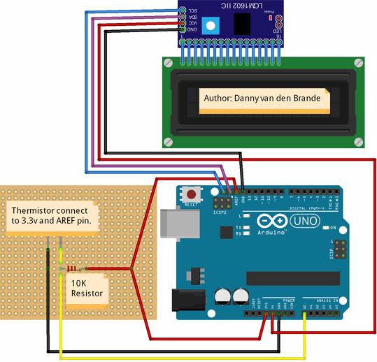
/*Author: Danny van den Brande, Arduinosensors.nl. BlueCore Tech.This code is written for the Thermistor, i attached a LCD1602A todisplay the temperature, you can change Celsius to fahrenheit below in the code.just uncomment line 73. you can use I2C or normal wiring. */// which analog pin to connect#define THERMISTORPIN A0 // resistance at 25 degrees C#define THERMISTORNOMINAL 10000 // temp. for nominal resistance (almost always 25 C)#define TEMPERATURENOMINAL 25 // how many samples to take and average, more takes longer// but is more 'smooth'#define NUMSAMPLES 5// The beta coefficient of the thermistor (usually 3000-4000)#define BCOEFFICIENT 3950// the value of the 'other' resistor#define SERIESRESISTOR 10000 //#include <LiquidCrystal.h> //uncomment when not using I2C#include <LiquidCrystal_I2C.h>//uncomment when using a I2C//LiquidCrystal lcd(12, 11, 5, 4, 3, 2); //Uncomment when not using a I2CLiquidCrystal_I2C lcd(0x27, 2, 1, 0, 4, 5, 6, 7, 3, POSITIVE);// Uncomment when using a I2C//make sure you set the right adress. here are the most common ones.//PCF8574 = 0x20, PCF8574A = 0x38, PCF8574AT = 0x3F. int samples[NUMSAMPLES]; void setup(void) { Serial.begin(9600); analogReference(EXTERNAL); lcd.begin(16,2); lcd.setCursor(2,0); lcd.print("Thermistor"); lcd.setCursor(1,1); lcd.print("BlueCore Tech"); delay(3000); lcd.clear();} void loop(void) { uint8_t i; float average; // take N samples in a row, with a slight delay for (i=0; i< NUMSAMPLES; i++) { samples[i] = analogRead(THERMISTORPIN); delay(10); } // average all the samples out average = 0; for (i=0; i< NUMSAMPLES; i++) { average += samples[i]; } average /= NUMSAMPLES; // Serial.print("Average analog reading "); // Serial.println(average);// convert the value to resistance average = 1023 / average - 1; average = SERIESRESISTOR / average;// Serial.print("Thermistor resistance "); // Serial.println(average); float steinhart; steinhart = average / THERMISTORNOMINAL; // (R/Ro) steinhart = log(steinhart); // ln(R/Ro) steinhart /= BCOEFFICIENT; // 1/B * ln(R/Ro) steinhart += 1.0 / (TEMPERATURENOMINAL + 273.15); // + (1/To) steinhart = 1.0 / steinhart; // Invert steinhart -= 273.15; // convert to Celsius// steinhart = (steinhart * 9.0)/ 5.0 + 32.0; // Uncomment if you want to use fahrenheit lcd.setCursor(2,0); lcd.print("Temperature "); // Serial.print("Temperature "); lcd.setCursor(3,1); lcd.print(steinhart);// Serial.print(steinhart); lcd.println(" *C ");//Comment when using fahrenheit// lcd.println(" *F ");//Uncomment when using fahrenheit// Serial.println(" *C");// Serial.println(" *F"); delay(1000);}
1.03 KY-888 Ultraconic - Distanzsensor HC-SR04
/*Author: Danny van den Brande, Arduinosensors.nl. BlueCore Tech.This code is made for the HC-SR04 Ultrasonic sensor.*/#include <LiquidCrystal.h> //#include <LiquidCrystal_I2C.h>//uncomment when using a I2C//LiquidCrystal_I2C lcd(0x27, 2, 1, 0, 4, 5, 6, 7, 3, POSITIVE);// Uncomment when using a I2C//make sure you set the right adress. here are the most common ones.//PCF8574 = 0x20, PCF8574A = 0x38, PCF8574AT = 0x3F.LiquidCrystal lcd(12, 11, 5, 4, 3, 2); int trig = 8; int echo = 9; void setup() { pinMode(trig, OUTPUT); pinMode(echo, INPUT); Serial.begin(9600); lcd.begin(16,2); lcd.setCursor(0,0); lcd.print("Afstand in cm:");}void loop() { long duration, distance; digitalWrite(trig, LOW); delayMicroseconds(2); digitalWrite(trig, HIGH); delayMicroseconds(10); digitalWrite(trig, LOW); duration = pulseIn(echo, HIGH); distance = (duration/2) / 29.1; lcd.setCursor(0,1); lcd.print(" "); // Serial.print(" "); lcd.setCursor(0,1); lcd.print(distance); lcd.print(" cm"); Serial.print(distance); Serial.println(" cm"); delay(250); }
KY-034
1.04 KY-034 7-color flash - 7-Farben LED-Modul
Blink
Turns on an LED on for two second, then off for two second, repeatedly.
This example code is in the public domain.
* /
void setup () {
/ / Initialize the digital pin as an output.
/ / Pin 13 has an LED connected on most Arduino boards:
pinMode (13, OUTPUT);
}
void loop () {
digitalWrite (13, HIGH); / / set the LED on
delay (2000); / / wait for a second
digitalWrite (13, LOW); / / set the LED off
delay (2000); / / wait for a second
}
1.05 KY-008 Laser emit - Laser-Transmitter Modul
SCHEMATIC
Pin - = GNDPin (middle pin) = not connectedPin S = +5V
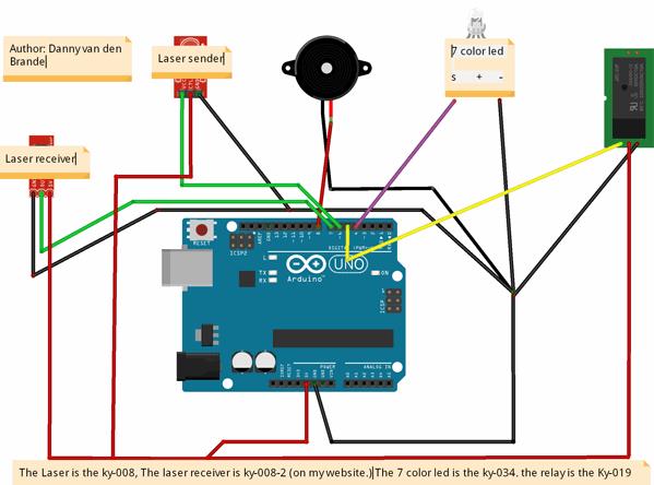
//Author Danny van den Brande. arduinosensors.nl, also check out my forum to find more info and example codes for most common sensors @ forum.arduinosensors.nl//Do whatever you want with this. //To keep the alarm running when triggered you need to do some modifications, but with this you got the basics to build from.//its just an example on how to build a cheap quality multifunctional alarm system.//Some ideas. // " Laser tripwire/alarm with relay. multifunctional "//* you can use it for an alarm, for burgelars, so a laser tripwire alarm as it is now.// you can attach a big RED light with a sound siren to the alarm with the relay or just a lamp or any device you wanna attach. //* you can build it inside a closet so when you open the door a lamp will go on, like a magnet lamp.//* you can build it inside a door of a selfmade car to make a door beep.//* You can build a SMOKE generator alarm with it. You your whole house will be filled with smoke using the relay + which turns on a attached smoke generator.//* you can also make a cool tripwire bomb from it for airsoft, i would not use it outside cuz a bug like a ant or fly could trigger it.//* You do not need to use the laser on the arduino you can use a external one, with external power.//* Its a very cheap multifunctional device, You can save a lot of money with this code and my Schematic.//* the laser sensors are for sale on my website, as well as the relay and 7 Color led.// // setup the pins hereint MulticolorLed = 4; // i used the 7 color led, just for the show. You can add any led or led module.//you can also remove the led module to save power, if the source comes from a battery.int Relay = 5;int LaserEmitter = 6; int LaserDetector = 7;int Buzzer = 8;// here i set up the tones, you can change them @ void loop.int tones[] = {261, 277, 293, 311, 329, 349, 369, 392, 415, 440, 466, 493, 523 ,554};// 1 2 3 4 5 6 7 8 9 10 11 12 13 14// You can add more tones but i added 14. Just fill in what tone you would like to use, @ void loop you see " tone(Buzzer, tones[12]); " below, digitalWrite(Buzzer, HIGH);// here you can change the tones by filling in a number between 1 and 14void setup(){ Serial.begin (9600);pinMode(LaserEmitter, OUTPUT);pinMode(LaserDetector, INPUT);pinMode(MulticolorLed, OUTPUT);pinMode(Buzzer, OUTPUT);digitalWrite(Buzzer, LOW);pinMode(Relay, OUTPUT);digitalWrite(Relay, LOW);//+++++++++++++++++++++++++++++++++++++++++++//Part of buzzer tonesfor (int i = 0; i < Buzzer; i++) {} }void loop(){digitalWrite(LaserEmitter, HIGH);boolean val = digitalRead(LaserDetector);Serial.println(val); // Open the Serial Monitor to see the valuesif (val == 0) // Here we set value to 0 with a if statement, because the laser sensor reads a value of 1 or 0. Its reads value 1 when the laser is aimed at the receiver. // so value 0 is what we set for this alarm right now. To change the alarm to a alarm that works the other way around you simply change this value to 1. // How would it work the other way around? well like a alarm you see in the movies that protects a diamond.. when the diamond or any item is removed the alarm will go off.{digitalWrite(Buzzer, HIGH); // here the Buzzer is set high in order to make a sound.tone(Buzzer, tones[6]); //here we set the tone by choosing from number 1 to 14delay (50);digitalWrite(Buzzer, LOW); // here we set the buzzer low and next we set noTone for the buzzer to make a break.noTone(Buzzer);delay (50); //this is the delay between each buzzer beep. You can play with the sounds by choosing from number 1 to 14digitalWrite(Buzzer, HIGH);tone(Buzzer, tones[9]);delay (100);digitalWrite(Buzzer, LOW);noTone(Buzzer);delay (100);digitalWrite(Buzzer, HIGH);tone(Buzzer, tones[14]);delay (50);digitalWrite(Buzzer, LOW);noTone(Buzzer);digitalWrite(MulticolorLed, HIGH); //Here we set the led to high, it will only flash when the alarm is triggereddelay(250);digitalWrite(Relay, HIGH); //here we set the relay to high, it will also only turn on when the laser is not aimed at the laser receiverdelay(100);}else //here we use the else statement to turn everything off when the if statement is reading the laser receivers value of 1{digitalWrite(Relay, LOW);// here everything turns off, so is set to low. This happens when the laser aims at the Laser receiver.digitalWrite(Buzzer, LOW);noTone(Buzzer);digitalWrite(MulticolorLed, LOW);}}
1.06 KY-999 Laser receiv - Laserempfänger
SCHEMATIC
Pin - = GNDPin (middle pin) = not connectedPin S = +5V
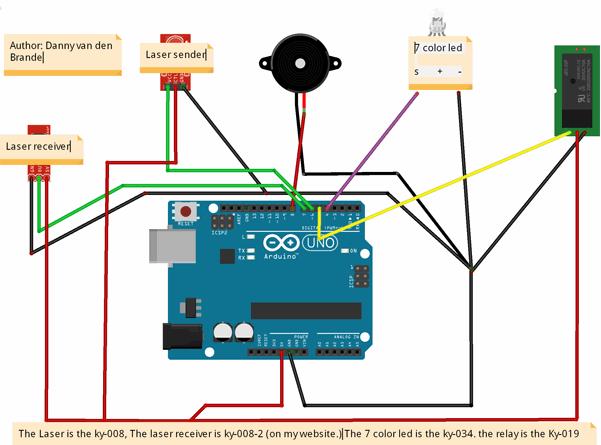
//Author Danny van den Brande. arduinosensors.nl, also check out my forum to find more info and example codes for most common sensors @ forum.arduinosensors.nl//Do whatever you want with this. I wrote it so you got my OK, :)//To keep the alarm running when triggered you need to do some modifications, but with this you got the basics to build from.//its just an example on how to build a cheap quality multifunctional alarm system.//Some ideas. // " Laser tripwire/alarm with relay. multifunctional "//* you can use it for an alarm, for burgelars, so a laser tripwire alarm as it is now.// you can attach a big RED light with a sound siren to the alarm with the relay or just a lamp or any device you wanna attach. //* you can build it inside a closet so when you open the door a lamp will go on, like a magnet lamp.//* you can build it inside a door of a selfmade car to make a door beep.//* You can build a SMOKE generator alarm with it. You your whole house will be filled with smoke using the relay + which turns on a attached smoke generator.//* you can also make a cool tripwire bomb from it for airsoft, i would not use it outside cuz a bug like a ant or fly could trigger it.//* You do not need to use the laser on the arduino you can use a external one, with external power.//* Its a very cheap multifunctional device, You can save a lot of money with this code and my Schematic.//* the laser sensors are for sale on my website, as well as the relay and 7 Color led.// // setup the pins hereint MulticolorLed = 4; // i used the 7 color led, just for the show. You can add any led or led module.//you can also remove the led module to save power, if the source comes from a battery.int Relay = 5;int LaserEmitter = 6; int LaserDetector = 7;int Buzzer = 8;// here i set up the tones, you can change them @ void loop.int tones[] = {261, 277, 293, 311, 329, 349, 369, 392, 415, 440, 466, 493, 523 ,554};// 1 2 3 4 5 6 7 8 9 10 11 12 13 14// You can add more tones but i added 14. Just fill in what tone you would like to use, @ void loop you see " tone(Buzzer, tones[12]); " below, digitalWrite(Buzzer, HIGH);// here you can change the tones by filling in a number between 1 and 14void setup(){ Serial.begin (9600);pinMode(LaserEmitter, OUTPUT);pinMode(LaserDetector, INPUT);pinMode(MulticolorLed, OUTPUT);pinMode(Buzzer, OUTPUT);digitalWrite(Buzzer, LOW);pinMode(Relay, OUTPUT);digitalWrite(Relay, LOW);//+++++++++++++++++++++++++++++++++++++++++++//Part of buzzer tonesfor (int i = 0; i < Buzzer; i++) {} }void loop(){digitalWrite(LaserEmitter, HIGH);boolean val = digitalRead(LaserDetector);Serial.println(val); // Open the Serial Monitor to see the valuesif (val == 0) // Here we set value to 0 with a if statement, because the laser sensor reads a value of 1 or 0. Its reads value 1 when the laser is aimed at the receiver. // so value 0 is what we set for this alarm right now. To change the alarm to a alarm that works the other way around you simply change this value to 1. // How would it work the other way around? well like a alarm you see in the movies that protects a diamond.. when the diamond or any item is removed the alarm will go off.{digitalWrite(Buzzer, HIGH); // here the Buzzer is set high in order to make a sound.tone(Buzzer, tones[6]); //here we set the tone by choosing from number 1 to 14delay (50);digitalWrite(Buzzer, LOW); // here we set the buzzer low and next we set noTone for the buzzer to make a break.noTone(Buzzer);delay (50); //this is the delay between each buzzer beep. You can play with the sounds by choosing from number 1 to 14digitalWrite(Buzzer, HIGH);tone(Buzzer, tones[9]);delay (100);digitalWrite(Buzzer, LOW);noTone(Buzzer);delay (100);digitalWrite(Buzzer, HIGH);tone(Buzzer, tones[14]);delay (50);digitalWrite(Buzzer, LOW);noTone(Buzzer);digitalWrite(MulticolorLed, HIGH); //Here we set the led to high, it will only flash when the alarm is triggereddelay(250);digitalWrite(Relay, HIGH); //here we set the relay to high, it will also only turn on when the laser is not aimed at the laser receiverdelay(100);}else //here we use the else statement to turn everything off when the if statement is reading the laser receivers value of 1{digitalWrite(Relay, LOW);// here everything turns off, so is set to low. This happens when the laser aims at the Laser receiver.digitalWrite(Buzzer, LOW);noTone(Buzzer);digitalWrite(MulticolorLed, LOW);}}
1.07 KY-002 Shock - Vibrations-Sensor - Schwingungs-Sensor
SCHEMATICPin - = GND, connect to GND of the ArduinoPin (middel pin) +5 v, connect to Arduino +5Pin S signal, connect to Arduino pin 6
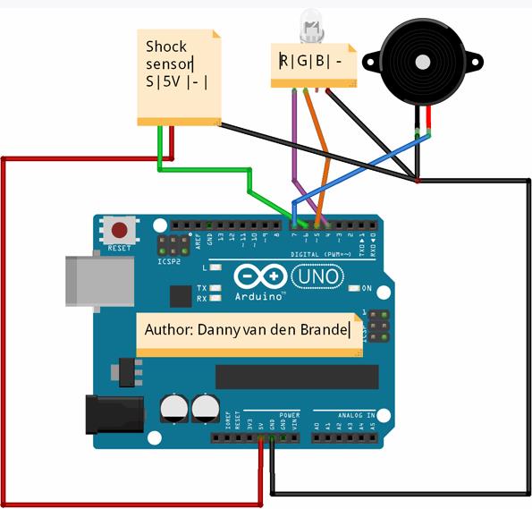
//Author: Danny van den Brande//This code is a basic code and a simple example on how to make a Earthquake alarm for example//Feel free to do what you want with this code.int GreenLed = 4;int RedLed = 5;int Shock = 6; int Buzzer = 7;int val; // define numeric variables val// here i set up the tones, you can change them @ void loop.int tones[] = {261, 277, 293, 311, 329, 349, 369, 392, 415, 440, 466, 493, 523 ,554};// 1 2 3 4 5 6 7 8 9 10 11 12 13 14// You can add more tones but i added 14. Just fill in what tone you would like to use, @ void loop you see " tone(Buzzer, tones[12]); " below, digitalWrite(Buzzer, HIGH);// here you can change the tones by filling in a number between 1 and 14void setup (){ pinMode (GreenLed, OUTPUT) ; pinMode (RedLed, OUTPUT) ; pinMode (Shock, INPUT) ; //vibration sensor pinMode (Buzzer, OUTPUT) ;}void loop (){ val = digitalRead (Shock) ; // Reads Digital Pin of sensor. if (val == HIGH) // When the shock sensor detects a signal, LED flashes { digitalWrite (RedLed, LOW); digitalWrite (GreenLed, HIGH); digitalWrite (Buzzer, LOW); } else { digitalWrite (RedLed, HIGH); digitalWrite (GreenLed, LOW); digitalWrite(Buzzer, HIGH); // here the Buzzer is set high in order to make a sound. tone(Buzzer, tones[6]); //here we set the tone by choosing from number 1 to 14 delay (50); digitalWrite(Buzzer, LOW); // here we set the buzzer low and next we set noTone for the buzzer to make a break. noTone(Buzzer); delay (50); //this is the delay between each buzzer beep. You can play with the sounds by choosing from number 1 to 14 digitalWrite(Buzzer, HIGH); tone(Buzzer, tones[9]); delay (100); digitalWrite(Buzzer, LOW); noTone(Buzzer); }}
1.08 KY-022 IR receiver / detector - Infrarot-Empfänger
SCHEMATIC:Arduino GND --> Module pin -Arduino +5V --> Module PLUS (middle pin)Arduino Digital pin 4 --> Module S
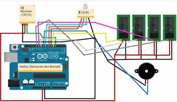
//Author: Danny van den Brande. ArduinoSensors.nl//Do what ever you want with this code!//Again a Multifuntional code, you can control your whole home with it if you want. I made a simple example on how to do this. Good luck!#include <IRremote.h> //Important to have the library installed! https://codebender.cc/library/IRremote int IRreceiver = 4; int Relay = 5; // You can add a 8 channel relay to, to control your home from 1 remote control for example. Just change the leds and buzzer to Relays.// i already set extra relays in the code so all you need to do is add them. Right now we have 10 11 and 12 USED, you can add 3 more relays.int Relay1 = 10;int Relay2 = 11;int Relay3 = 12;int RedLed = 6;int GreenLed = 7;int BlueLed = 8;int Buzzer = 9;int OnOrOFF[] = {0,0,0,0,0,0,0,0,0,0}; //If you add a button, then add a ,0 here for each button you add.//Here we Define the buttons, if you are using a different remote then the HX1838 that i used open serial monitor and press the desired buttons.//change the numbers you see in the serial monitor here below, and asign a button to that number..#define Button1 48703 // button 1 #define Button2 58359 // button 2#define Button3 539 // button 3#define Button4 25979 // button 4#define Button5 15547 // button 5#define Button6 59295 // button 6#define Button7 65015 // button 7#define Button8 5499 // button 8#define AllonOff 19899 // Play/Pauze on the HX1838 Switches Off or On everything. IRrecv irrecv(IRreceiver); decode_results results; void setup(){ Serial.begin(9600); irrecv.enableIRIn(); pinMode (Relay, OUTPUT); pinMode (Relay1, OUTPUT); pinMode (Relay2, OUTPUT); pinMode (Relay3, OUTPUT); pinMode (BlueLed, OUTPUT); pinMode (RedLed, OUTPUT); pinMode (GreenLed, OUTPUT); pinMode (Buzzer, OUTPUT);} void loop() { if (irrecv.decode(&results)) { unsigned int value = results.value; switch(value) { // HERE YOU SET THE BUTTONS, you can add more buttons just copy new sections. // Just copy what is between "case Button1 and case button 2. make sure you also change if(OnOrOFF[1]<--(change the number to 10 in this case.) Because button 9 (the AllonOff button) // is number 9 right right now, which is asigned to the Pauze/Play button on the remote control. If you place another button after that it would be Button 11, and so on.// case Button10: This would be the next button.// if(OnOrOFF[10] == 1) { //<--- Just copy this section and paste it below the latest button.// digitalWrite(BlueLed, LOW); // OFF// OnOrOFF[10] = 0; // } else { // digitalWrite(BlueLed, HIGH); // ON// OnOrOFF[10] = 1; // }// break; <-- make sure you copy this to. case Button1: if(OnOrOFF[1] == 1) { digitalWrite(BlueLed, LOW); // OFF OnOrOFF[1] = 0; } else { digitalWrite(BlueLed, HIGH); // ON OnOrOFF[1] = 1; } break; case Button2: if(OnOrOFF[2] == 1) { digitalWrite(RedLed, LOW); OnOrOFF[2] = 0; } else { digitalWrite(RedLed, HIGH); OnOrOFF[2] = 1; } break; case Button3: if(OnOrOFF[3] == 1) { digitalWrite(GreenLed, LOW); OnOrOFF[3] = 0; } else { digitalWrite(GreenLed, HIGH); OnOrOFF[3] = 1; } break; case Button4: if(OnOrOFF[4] == 1) { digitalWrite(Buzzer, LOW); OnOrOFF[4] = 0; } else { digitalWrite(Buzzer, HIGH); OnOrOFF[4] = 1; } break; case Button5: if(OnOrOFF[5] == 1) { digitalWrite(Relay, LOW); // START OF RELAYS OnOrOFF[5] = 0; } else { digitalWrite(Relay, HIGH); OnOrOFF[5] = 1; } break; case Button6: if(OnOrOFF[6] == 1) { digitalWrite(Relay1, LOW); OnOrOFF[6] = 0; } else { digitalWrite(Relay1, HIGH); OnOrOFF[6] = 1; } break; case Button7: if(OnOrOFF[7] == 1) { digitalWrite(Relay2, LOW); OnOrOFF[7] = 0; } else { digitalWrite(Relay2, HIGH); OnOrOFF[7] = 1; } break; case Button8: if(OnOrOFF[8] == 1) { digitalWrite(Relay3, LOW); OnOrOFF[8] = 0; } else { digitalWrite(Relay3, HIGH); OnOrOFF[8] = 1; } break; case AllonOff: if(OnOrOFF[9] == 1) { digitalWrite(Buzzer, LOW); digitalWrite(Relay, LOW); digitalWrite(Relay1, LOW); digitalWrite(Relay2, LOW); digitalWrite(Relay3, LOW); digitalWrite(GreenLed, LOW); digitalWrite(RedLed, LOW); digitalWrite(BlueLed, LOW); OnOrOFF[9] = 0; } else { digitalWrite(Buzzer, HIGH); digitalWrite(Relay, HIGH); digitalWrite(Relay1, HIGH); digitalWrite(Relay2, HIGH); digitalWrite(Relay3, HIGH); digitalWrite(GreenLed, HIGH); digitalWrite(RedLed, HIGH); digitalWrite(BlueLed, HIGH); OnOrOFF[9] = 1; } break; //<<--- this is the spot where you paste a new button. } Serial.println(value); irrecv.resume(); }}
1.09 KY-005 IR emision / emitter - Infrarot-Sender
# Include <IRremote.h>
int RECV_PIN = 11; / / define input pin on Arduino
IRrecv irrecv (RECV_PIN);
decode_results results;
void setup ()
{
Serial.begin (9600);
irrecv.enableIRIn (); / / Start the receiver
}
void loop () {
if (irrecv.decode (& results)) {
Serial.println (results.value, HEX);
irrecv.resume (); / / Receive the next value
}
}
Main emission part of the code:
# Include <IRremote.h>
IRsend irsend;
void setup ()
{
Serial.begin (9600);
}
void loop () {
for (int i = 0; i <50; i + +) {
irsend.sendSony (0xa90, 12); / / Sony TV power code
delay (40);
}
}
1.10 KY-032 Tracking - IR-Reflex-Sensor - Hindernisvermeidungssensor
SIEHE auf einer anderen Seite
KY-032 Tracking - Linienverfolgungs-Sensor
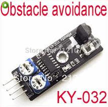
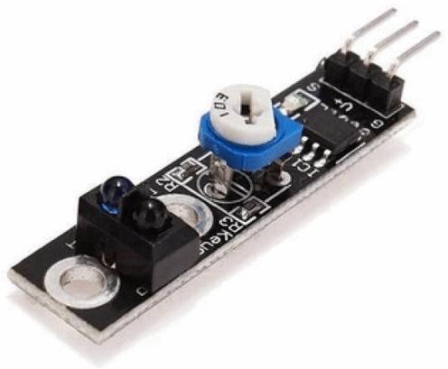
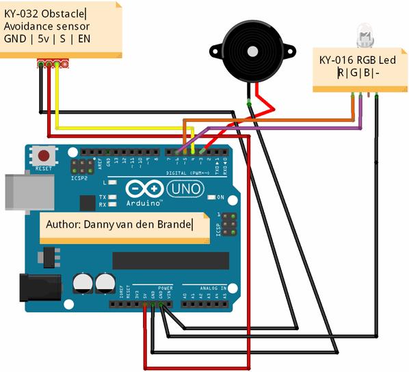
//Author: Danny van den Brande. BlueCore Tech. Arduinosensors.nl//This is an example code on how to use the obstacle avoidance sensor KY-032//This sensor works the same as warning sensors in cars. Used in many robot projects.int Buzzer = 3;int AvoidancePin = 4; // define the obstacle avoidance sensor interfaceint RedLed = 5 ;int GreenLed = 6 ;int val ;// Value High or LOW. // here i set up the tones, you can change them @ void loop.int tones[] = {261, 277, 293, 311, 329, 349, 369, 392, 415, 440, 466, 493, 523 ,554};// 1 2 3 4 5 6 7 8 9 10 11 12 13 14// You can add more tones but i added 14. Just fill in what tone you would like to use, @ void loop you see " tone(Buzzer, tones[12]); " below, digitalWrite(Buzzer, HIGH);// here you can change the tones by filling in a number between 1 and 14void setup (){ Serial.begin (9600); pinMode (RedLed, OUTPUT) ; pinMode (GreenLed, OUTPUT) ; pinMode (Buzzer, OUTPUT) ; pinMode (AvoidancePin, INPUT) ;// define the obstacle avoidance sensor output interface}void loop (){ val = digitalRead (AvoidancePin) ;// Reading from the AvoidancePin if (val == HIGH) { digitalWrite (RedLed, LOW); digitalWrite (GreenLed, HIGH); digitalWrite (Buzzer, LOW); noTone(Buzzer); delay(100); } else { digitalWrite (RedLed, HIGH); digitalWrite (GreenLed, LOW); digitalWrite (Buzzer, HIGH); tone(Buzzer, tones[6]);//You can change the tone choosing from 1 to 14. delay(100); }}
1.11 KY-031 Top module - Erschütterungs-Sensor - Schlag-Sensor-Modul
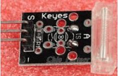
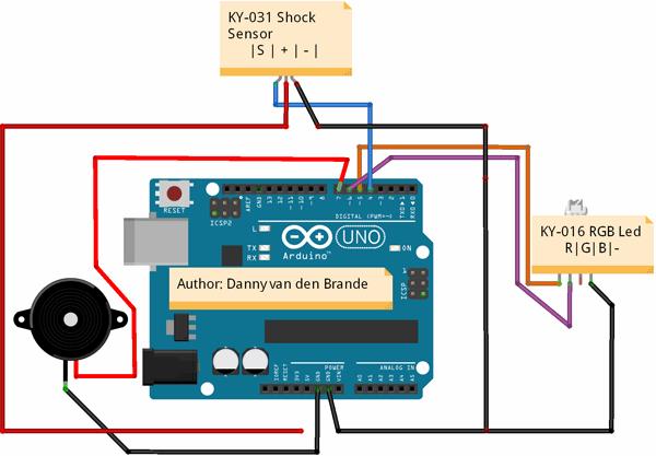
//Author: Danny van den Brande, arduinosensors.nl//This is a example of what you can do with the shock sensor.//I made a simple mailbox alert project.//Offcourse this can be used to detect anything else that produces a shock.int ShockSensor = 4;int RedLed = 5;int GreenLed = 6;int Buzzer = 7;int value = HIGH;boolean Alarm = false;unsigned long LatestKnockTime; int TriggerTime = 25; //You can change this if you want the alarm to trigger longer.void setup (){ Serial.begin(9600); pinMode (ShockSensor, INPUT) ; //the sensor set to input pinMode (Buzzer, OUTPUT); pinMode (RedLed, OUTPUT); pinMode (GreenLed, OUTPUT);}void loop (){ value = digitalRead (ShockSensor) ; // Reading value if (value == LOW) { LatestKnockTime = millis(); // if (!Alarm){ Serial.println("Shock detected");// You can add a lcd and make it print on LCD digitalWrite (GreenLed, HIGH); digitalWrite (Buzzer, HIGH); delay(1000); digitalWrite (Buzzer, LOW); delay(1000); digitalWrite (Buzzer, HIGH); delay(1000); digitalWrite (Buzzer, LOW); delay(1000); digitalWrite (Buzzer, HIGH); delay(1000); digitalWrite (Buzzer, LOW); delay(1000); digitalWrite (Buzzer, HIGH); delay(1000); digitalWrite (Buzzer, LOW); delay(1000); Alarm = true; } } else { if( (millis()-LatestKnockTime) > TriggerTime && Alarm){ Serial.println("Nothing Detected"); digitalWrite (Buzzer, LOW); Alarm = false; } }}
1.12 KY-010 Light blocking - Gabel-Lichtschranke
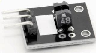
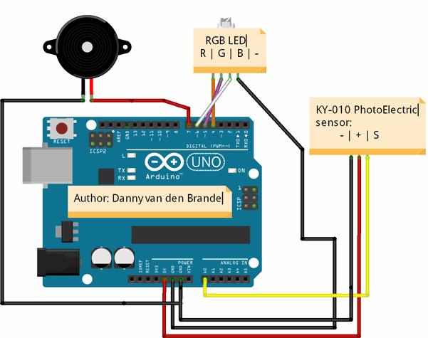
//Author: Danny van den Brande, arduinosensors.nl//Hello world! I made a simpel example on what you can do with the KY-010//In this case we made a simpel alarm with a piece of plastic, //i used a atm card to put in the sensor any piece of plastic will work, //when you remove it the alarm will trigger and print a value and text in the serial monitor. //You can make it print on a lcd to, or for more advanced stuff make it send a sms or add relays, whatever you want it to do! int PhotoElectricSensor = A0; int buzzer = 7;int RedLed = 4;int GreenLed = 5;int BlueLed = 6;int val ;void setup (){ Serial.begin(9600); pinMode (buzzer, OUTPUT) ; pinMode (RedLed, OUTPUT) ; pinMode (GreenLed, OUTPUT) ; pinMode (BlueLed, OUTPUT) ;}void loop (){ val = analogRead (PhotoElectricSensor) ; Serial.print(val);// printing the value in the serial monitor if(val < 50&& val < 500) { Serial.println(" ATM CARD NOT PLACED");// Open the serial monitor to see this. digitalWrite (GreenLed, LOW); alarmsound(10);// Change if you want the alarm to last longer if card is removed } else if (val > 500 && val < 1023) { Serial.println(" ATM CARD IN PLACE");// the alarm will not trigger and the green led will be on. digitalWrite (GreenLed, HIGH); } delay(1000);}void alarmsound(int duration){ // alarm section, alarm will flash red and blue when trigger, if not it will stay green. for (int p = 0; p < duration; p++){for (int i = 0; i <80; i++) { digitalWrite (buzzer, HIGH) ; digitalWrite (RedLed, HIGH) ; delay (1) ; digitalWrite (buzzer, LOW) ; digitalWrite (RedLed, LOW) ; delay (1) ; } for (int i = 0; i <100; i++) { digitalWrite (buzzer, HIGH) ; digitalWrite (BlueLed, HIGH) ; delay (1) ; digitalWrite (buzzer, LOW) ; digitalWrite (BlueLed, LOW) ; delay (1) ; } } }
1.13 KY-040 Rotary encoders - Drehimpuls-Geber
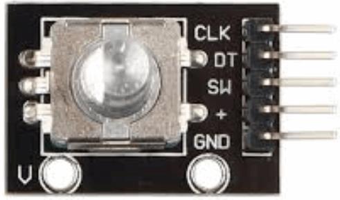
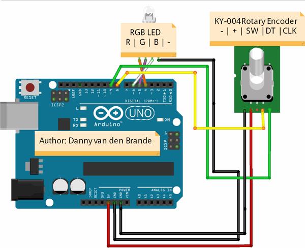
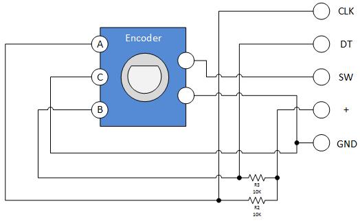
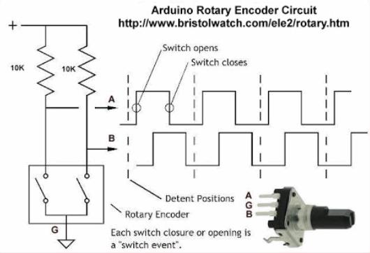
/* Author: Danny van den Brande, Arduinosensors.nl This is a example on how to use the KY-040 Rotary encoder. Its very basic but if your new to arduino or could not find any code, then you have something to start with. because there is little documentation about the KY sensor kit. */ int CLK = 9; // Pin 9 to clk on encoder int DT = 8; // Pin 8 to DT on encoder int RedLed = 4;// You do not need to use the leds. // you can take a look in the serial monitor if you dont have leds. // there it will display values. int GreenLed = 5; int BlueLed = 6; int RotPosition = 0; int rotation; int value; boolean LeftRight; void setup() { Serial.begin (9600); pinMode (CLK,INPUT); pinMode (DT,INPUT); pinMode (RedLed, OUTPUT); pinMode (GreenLed, OUTPUT); pinMode (BlueLed, OUTPUT); rotation = digitalRead(CLK); } void loop() { value = digitalRead(CLK); if (value != rotation){ // we use the DT pin to find out which way we turning. if (digitalRead(DT) != value) { // Clockwise RotPosition ++; LeftRight = true; } else { //Counterclockwise LeftRight = false; RotPosition--; } if (LeftRight){ // turning right will turn on red led. Serial.println ("clockwise"); digitalWrite (RedLed, HIGH); digitalWrite (GreenLed, LOW); }else{ // turning left will turn on green led. Serial.println("counterclockwise"); digitalWrite (RedLed, LOW); digitalWrite (GreenLed, HIGH); } Serial.print("Encoder RotPosition: "); Serial.println(RotPosition); // this will print in the serial monitor. } rotation = value; }
1.14 KY-006 Passive buzzer - Piezo-Lautsprecher
ConnectingArduino digital pin 8 --> pin 'S' of module Arduino GND --> Pin '-' of module
int buzzer = 8 ;// setting controls the digital IO foot buzzer
void setup ()
{
  pinMode (buzzer, OUTPUT) ;// set the digital IO pin mode, OUTPUT out of Wen
}
void loop ()
{
  unsigned char i, j ;// define variables
  while (1)
  {
    for (i = 0; i <80; i++) // Wen a frequency sound
    {
      digitalWrite (buzzer, HIGH) ;// send voice
      delay (1) ;// Delay 1ms
      digitalWrite (buzzer, LOW) ;// do not send voice
      delay (1) ;// delay ms
    }
    for (i = 0; i <100; i++) // Wen Qie out another frequency sound
    {
      digitalWrite (buzzer, HIGH) ;// send voice
      delay (2) ;// delay 2ms
      digitalWrite (buzzer, LOW) ;// do not send voice
      delay (2) ;// delay 2ms
    }
  }
}
https://rydepier.wordpress.com/tag/buzzer/
1.15 KY-012 buzzer - Active Buzzer Modul
SCHEMATIC:
Module pin - = GND Module pin S = +5VConnection to Arduino
-
Arduino GND --> Module pin -
-
Arduino digital pin 8 --> Module pin S
int speakerPin = 8;
void setup () {
  pinMode (speakerPin, OUTPUT);
}
void loop () {
  analogWrite (speakerPin, 255);
  delay (50);
  analogWrite (speakerPin, 0);
  delay (10);
}
Quelle:
http://arduinosensors.nl/index.php?route=product/category&path=20&page=1
http://arduinosensors.nl/index.php?route=product/category&path=20
DIN A4 ausdrucken
*********************************************************
Impressum: Fritz Prenninger, Haidestr. 11A, A-4600 Wels, Ober-Österreich, mailto:[email protected]
ENDE
|
