http://sites.schaltungen.at/arduino-uno-r3/waage-mit-dms/hx711-a-d-wandler
http://www.linksammlung.info/
http://www.schaltungen.at/
Wels, am 2019-07-31
BITTE nützen Sie doch rechts OBEN das Suchfeld [ ] [ Diese Site durchsuchen]
DIN A3 oder DIN A4 quer ausdrucken
*******************************************************************************I**
DIN A4 ausdrucken siehe http://sites.schaltungen.at/drucker/sites-prenninger
********************************************************I*
~015_b_PrennIng-a_arduino.uno.r3-waage.mit.dms-hx711.a.d.wandler (xx Seiten)_1a.pdf fehlt
Untergeordnete Seiten (1):
1kg DMS Wiegesensor
Ils - HX711 24bit AD Module + 1kg Aluminum Alloy Scale Weighing Sensor Load Cell Kit for Arduino € 9,26 + Porto € 3,99
haljia Tragbarer Elektronischer Gewicht Sensor Wägezelle Sensor (1kg)
+
HX711 Gewicht Sensoren AD Modul für Arduino
1kg Aluminum Alloy Scale Weighing Sensor vorh.
TinkerForge Wägezelle 1kg
-
Dieses Modul verwendet 24 High Präzision A/D Converter Chip HX711.
-
Es ist ein speziell für die hochpräzise elektronische Skala Design mit zwei Analog Input channelthe interne Integration der 128 mal der programmierbare Gain Verstärker.
-
Die Eingangsleistung Schaltung kann so konfiguriert werden, bieten eine Brücke Art Druck Brücke (wie pressureweighing Sensor-Modus) ist der hohe precisionlow Kosten ist eine ideale Probenahme Front-End-Modul.
-
Vier führt, einfach zu bedienen, 5..10V Spannung aufgetragen, die Kraft direkt Ausgang als Spannung ändern Signal ist.
-
Maße: 12,7x12,7x80mm
-
Bereich: 1 kg
ILS - HX711 24bit AD Module vorh.
Load Cell Amplifier - HX711
Wägezellen-Verstärker HX711
24-bit Analog-to-Digital Converter (ADC) for Weigh Scales HX711
300_d_AVIA-x_24-bit Analog-to-Digital Converter (ADC) for Weigh Scales (DMS) - HX711 Datenblatt_1a.pdf
HX711 pin description
Pin # Name Function Description
1 VSUP Power Regulator supply: 2.7 ~ 5.5V
2 BASE Analog Output Regulator control output(NC when not used)
3 AVDD Power Analog supply: 2.6 ~ 5.5V
4 VFB Analog Input Regulator control input(connect to AGND when not used)
5 AGND Ground Analog Ground
6 VBG Analog Output Reference bypass output
7 INA- Analog Input Channel A negative input
8 INA+ Analog Input Channel A positive input
9 INB- Analog Input Channel B negative input
10 INB+ Analog Input Channel B positive input
11 PD_SCK Digital Input Power down control (high active) and serial clock input
12 DOUT Digital Output Serial data output
13 XO Digital I/O Crystal I/O (NC when not used)
14 XI Digital Input Crystal I/O or external clock input, 0: use on-chip oscillator
15 RATE Digital Input Output data rate control, 0: 10Hz; 1: 80Hz
16 DVDD Power Digital supply: 2.6 ~ 5.5V
https://www.instructables.com/id/How-to-Interface-HX711-Balance-Module-With-Load-Ce/
https://www.brainy-bits.com/load-cell-and-hx711-with-arduino/
Produktbeschreibungen
Eigenschaften:
Zwei wählbare Differential Eingangskanäle
Chip aktiv geringe Geräusch PGA mit wählbarer Verstärkung von 3264 und 128
Chip Power Supply Regulator für load-cell und ADC Analog Stromversorgung
Audiosignals on-Chip Oszillator keine externe Komponente mit optionalen externen Kristall
on-chip power-on-reset
Einfache digitale Steuerung und serieller Schnittstelle: pin-driven controlsno Programmierung erforderlich
Wählbare 10SPS oder 80SPS Ausgabe Datenrate
Gleichzeitige Versorgung mit 50 und 60 Hz Ablehnung
Stromverbrauch inkl. Chip Analog Netzteil Regler: Normalbetrieb < 1,5 mAPower Down < 1uA
Operation Versorgungsspannung: 2.6 ~ 5.5 V
Temperaturbereich: von -20 Grad bis + 85 Grad
Wägezelle Größe: 80x12,7x12,7mm
Gewicht 31,8g
Modulgröße: 24x16mm
Anschluss:
Rot zu e +
Schwarz zu e
Grün auf A +
weiß A
Lieferumfang:
1 x Gewicht Sensor 1kg
1 x HX711 24-bit Precision ADC MODULE
https://www.amazon.de/gp/product/B0769FZ7NB?ref=em_1p_2_ti&ref_=pe_22146771_394007011
5 Stk. 350 Ohm Dehnungsmeß-Streifen DMS
Haljia BF350 BF350-3AA Elektrischer Widerstand mit Dehnungsmessstreifen, 350 Ohm für Belastungssensor für Dehnungsmessstreifen,
Arduino Weighing Scale with Load Cell and HX711
- red (Excitation+ or Vcc)
- black (Excitation- or GND)
- white (Amplifier+, Signal+, or Output+)
- green (A-, S-, or O-)
- yellow (Shield)
HX711 Load Cell Amplifier Product Code : RB-Spa-1359 by Sparkfun Electronics
SparkFun HX711 Load Cell Amplifier v11 SEN-13230
https://www.robotshop.com/media/files/pdf/hx711-load-cell-amplifier-schematic.pdf
Einführung
- Laden Sie Zellen und Arduino-Bibliothek
- Teileliste und Verkabelung
- Kalibriermethode und Prüfung
Fazit
Eine Wägezelle ist eine Anwendung von Dehnungsmessungen im Zusammenhang mit der Gewichtsmessung.
Eine Last wird auf einen Dehnungsmessstreifen aufgebracht, wodurch der Dehnungsmessstreifen einen bestimmten Betrag belastet und eine der aufgebrachten Last proportionale Spannung ausgibt.
Diese Beziehung zwischen Dehnung und Spannung wird in vielen Anwendungen verwendet, in denen die Gewichtsmessung wichtig ist. Wägezellen sind aufgrund ihrer Linearität, Kosteneffizienz und einfachen Implementierung sehr verbreitet.
In diesem Tutorial stelle ich eine Arduino-kompatible Wägezelle vor, die alle oben genannten Vorteile veranschaulicht.
Ich werde auch die Kalibrierung mit bekannten Massen einführen, um ein leistungsstarkes und genaues Wiegesystem zu erstellen, das für hochgenaue Messzwecke verwendet werden kann,
z. B .: Chemie, Gartenbau, Kochen und vieles mehr!
Laden Sie Zellen und Arduino-Bibliothek
Ein 24-bit Analog-Digital-Wandler namens HX711 wandelt die kleinen Änderungen der Belastung von der Wägezelle in 24-bit Änderungen der Spannung (Arduino 0-5V) um.
Auf diese Weise kann der Arduino Gewichts- (Massen-) Änderungen bis in den Bereich der Wägezelle (normalerweise 500 g, 1 kg, 5 kg oder mehr) dividiert durch die Hälfte der Bittiefe (223) auflösen.
Bei einer 1 kg-Wägezelle führt dies zu einer Massenänderungserkennung von bis zu 0,0001 g.
In der Praxis können jedoch sowohl der Analog-Digital-Wandler als auch die Wägezelle inhärentes Rauschen aufweisen (elektrisch und mechanisch), was zu einer viel geringeren Genauigkeit führt, die näher an 0,1% des Messwerts liegt - was wir später anhand von Messungen untersuchen und quantifizieren werden in diesem Tutorial.
In diesem Lernprogramm verwende ich eine kompakte HX711-Wägezellenbibliothek von Queuetue mit dem Namen "<Q2HX711.h>".
Es wurde festgestellt, dass die Verwendung dieser Bibliothek am einfachsten und leistungsmäßigsten zu implementieren ist.
Um die Bibliothek herunterzuladen, rufen Sie den Bibliotheksmanager in der Arduino IDE auf und geben Sie HX711 ein.
In diesem Tutorial wird die 'Queuetue HX711 Library' verwendet, und das verwendete Programm basiert auf ihrem Beispiel.
Das einfache Beispiel des HX711 zeigt die grundlegenden Funktionen, mit denen die Waage funktioniert.
Unten ist der Beispielcode / Sketch:
#include <Q2HX711.h>const byte hx711_data_pin = 3;const byte hx711_clock_pin = 4;Q2HX711 hx711(hx711_data_pin, hx711_clock_pin);void setup() { Serial.begin(9600);}void loop() { Serial.println(hx711.read()/100.0); delay(500);}
Nachdem Sie den obigen Code hochgeladen und den HX711 ordnungsgemäß mit dem Arduino verbunden und sichergestellt haben, dass der HX711 ordnungsgemäß mit der Wägezelle verbunden ist, sollte der Code einen Wert nahe der Hälfte von 224 ausgeben.
Auf diese Weise kann die Wägezelle sowohl die positive als auch die negative Last messen .
Positive Last addiert sich zu Masse, und negative Last repräsentiert die Kraftmessdose, die in die entgegengesetzte Richtung der Schwerkraft belastet wird.
Teileliste und Verkabelung
Der HX711 kann von 2,7 V bis 5,5 V betrieben werden.
Das vollständige Datenblatt mit Spezifikationen für den HX711 finden Sie hier. Ich werde keine Änderungen an der HX711-Bibliothek vornehmen, daher sind die oben genannten Aussagen das Ausmaß, in dem ich den HX711 erörtern werde, abgesehen von der Verkabelung.
Die in diesem Experiment verwendeten Hauptteile sind:
Arduino Uno - $11.00 [Our Shop]
1kg Load Cell + HX711 - $12.99 [ Our Shop]
Jumper Wires - $5.99 [ Amazon]
Calibrated Weights - $9.99 [ Amazon]
Der HX711 kann einfach mit zwei beliebigen digitalen oder analogen Pins mit dem Arduino verbunden werden.
Die Wägezelle muss außerdem genau mit dem HX711 verdrahtet sein, um sicherzustellen, dass die entsprechenden Dehnungsmessstreifen verwendet werden, um das von der Wägezelle angegebene Gewicht zu approximieren.
Als nächstes werden wir die Kalibrierung untersuchen und die Wägezelle als Waage testen.
Kalibriermethode und Prüfung
Die Wägezelle ist sehr empfindlich und abhängig von der sich ändernden Umgebung kann eine Kalibrierung erforderlich sein.
Ich werde eine Methode mit zwei Kalibrierungspunkten skizzieren: dem Nullwert (Tara) und einem kalibrierten Massenwert.
Die kalibrierte Massenmethode stellt sicher, dass die Wägezelle bei jeder Verwendung mit einer bekannten Masse kalibriert wird, wodurch die bestmögliche Annäherung an die Masse von Objekten mit unbekannter Masse sichergestellt wird.
Ich empfehle die Kalibrierung vor jedem Gebrauch und immer dann, wenn sich die Umgebung ändert oder die Wägezelle bewegt wird.
Anhand der Gleichung für eine Linie können wir verstehen, wie die Kalibrierung stattfinden wird und wie wir die Kalibrierung mit einer Arduino-Platine und einer Wägezelle spezifisch implementieren. Die Gleichung für eine Linie lautet:
[\ large y = mx + b]
Dabei ist x der Messwert des ADC des HX711, y die bekannte Masse, m die Steigung der Kalibrierungslinie und b der Achsenabschnitt, in dem y = 0 ist, was auch der Tarapunkt ist, wenn keine Masse vorhanden ist wird der Skala hinzugefügt.
Wenn Dummy-Punkte x0, y0 als ein Punkt auf der Linie und x1, y1 als der zweite Punkt auf der Linie verwendet werden:
Da Dehnungsmessstreifen die Dehnung linear mit der ausgeübten Kraft in Beziehung setzen, können wir beim Kalibrieren der Wägezelle eine lineare Beziehung verwenden.
Ich habe auch verschiedene kalibrierte Massen gegen die Anzeige der Wägezelle HX711 aufgetragen, um diese Linearität bei mehreren Dehnungen zu überprüfen.
Diese Handlung ist unten dargestellt:
Die Linearität über mehrere Massen versichert uns, dass die Zweipunktkalibrierungsmethode ausreicht!
Der einfachste Weg, die Kalibrierung zu verstehen, besteht darin, den ADC-Messwert des HX711 ohne zusätzliche Masse (Tara) zu verwenden.
Sobald der Nullwert kalibriert ist, bitten Sie Arduino, den HX711-ADC-Wert mit einer bekannten Kalibrierungsmasse erneut zu lesen.
Auf diese Weise werden eine aktuelle lineare Kalibrierungsneigung und ein aktueller Achsenabschnitt erstellt, um ein möglichst genaues Wiegen zu gewährleisten.
Der folgende Code beschreibt diesen Prozess.
#include <Q2HX711.h>const byte hx711_data_pin = 3;const byte hx711_clock_pin = 4;float y1 = 20.0; // calibrated mass to be addedlong x1 = 0L;long x0 = 0L;float avg_size = 10.0; // amount of averages for each mass measurementQ2HX711 hx711(hx711_data_pin, hx711_clock_pin); // prep hx711void setup() { Serial.begin(9600); // prepare serial port delay(1000); // allow load cell and hx711 to settle // tare procedure for (int ii=0;ii<int(avg_size);ii++){ delay(10); x0+=hx711.read(); } x0/=long(avg_size); Serial.println("Add Calibrated Mass"); // calibration procedure (mass should be added equal to y1) int ii = 1; while(true){ if (hx711.read()<x0+10000){ } else { ii++; delay(2000); for (int jj=0;jj<int(avg_size);jj++){ x1+=hx711.read(); } x1/=long(avg_size); break; } } Serial.println("Calibration Complete");}void loop() { // averaging reading long reading = 0; for (int jj=0;jj<int(avg_size);jj++){ reading+=hx711.read(); } reading/=long(avg_size); // calculating mass based on calibration and linear fit float ratio_1 = (float) (reading-x0); float ratio_2 = (float) (x1-x0); float ratio = ratio_1/ratio_2; float mass = y1*ratio; Serial.print("Raw: "); Serial.print(reading); Serial.print(", "); Serial.println(mass);}
Eine Demo des Waagenprogramms ist ebenfalls unten dargestellt:
Verfahren zur Verwendung des oben genannten Wiegeprogramms:
1. Starten Sie das Programm mit nichts auf der Wägezellenplattform neu
2. Öffnen Sie die serielle Schnittstelle
3. Warten Sie, bis die Tara beendet ist und Arduino den Ausdruck „Add Calibrated Mass“ (Kalibrierte Masse hinzufügen) erstellt hat.
4. Fügen Sie eine kalibrierte Masse hinzu, die dem obigen Variablenwert "y1" entspricht (20 g in meinem Fall).
5. Warten Sie auf den Ausdruck: "Kalibrierung abgeschlossen"
6. Echtzeitmasse sollte ausgedruckt werden!
Fazit
In diesem Tutorial wurden Wägezellen und Dehnungsmessstreifen vorgestellt, um die Masse unter Verwendung der Linearität von Dehnungsmessstreifen und unter Ausnutzung der Erdanziehung zu approximieren.
Mit bekannten kalibrierten Massen konnten wir ein Routing erstellen, das die Wägezelle und die ungefähre Masse kalibriert.
Diese Waagenroutine wurde in Echtzeit implementiert, um eine hochpräzise Waage zu erstellen, die sowohl tragbar als auch kostengünstig ist - alle mit Arduino- und Arduino-kompatiblen Komponenten.
Mit der Wägezellenwaage können Sie die Dehnung in Echtzeit messen und Ingenieure in die Lage versetzen, Änderungen von Masse und Gewicht aufzuzeichnen und letztendlich zu untersuchen.
*******************************************************************************I**
http://www.mschoeffler.de/
Fritzing zeigt, wie die Wägezelle an das HX711-Modul angeschlossen wird.
Darüber hinaus wird gezeigt, wie das HX711-Modul und das LCM1602 IIC v1 (LCD) -Modul mit dem Arduino verbunden werden.
In diesem Tutorial wird gezeigt, wie ein Arduino Uno, ein HX711-Breakout-Board und eine Wägezelle zum Messen des Gewichts verwendet werden.
Darüber hinaus wird ein LCD-Modul vom Typ LCM1602 IIC V1 zur Anzeige des gemessenen Gewichts verwendet.
Liste der Materialien:
- Arduino Uno [Suchen Sie auf Aliexpress | Amazonas]
- Überbrückungsdrähte [Suchen Sie auf Aliexpress | Amazonas]
HX711 wägezelle verstärker [Suchen auf Aliexpress | Amazonas]
Wägezelle [Suchen auf Aliexpress | Amazonas]
- LCM1602 IIC V1 (LCD) [Suchen auf Aliexpress | Amazonas]
- Kleine Kanthölzer und Schrauben
Der HX711 ist ein 24-Bit-Analog-Digital-Wandler, der sich perfekt für Waagenanwendungen eignet. Glücklicherweise gibt es für den HX711 viele Breakout-Boards.
Daher ist es sehr einfach, es in Kombination mit einer sogenannten Wägezelle zu verwenden. Wägezellen sind Wandler, die Druck / Kraft in ein elektrisches Signal umwandeln.
Da das elektrische Signal typischerweise nur wenige Millivolt hat, muss es verstärkt werden.
Und hier kommt das Breakout-Board HX711 ins Spiel:
Es verstärkt das schwache Signal auf einige Volt, damit wir das Signal mit Hilfe eines Arduino Uno lesen können.
Vorbereitungen für die Verdrahtung:
Um die Wägezelle einfach an die Pins des HX711-Moduls anzuschließen, können Sie den Drähten DuPont-Steckverbinder hinzufügen.
Dieser Schritt ist völlig optional. Sie können alles verwenden, um die Drähte mit den Stiften des Moduls zu verbinden.
Beachten Sie bei der Verwendung von DuPont-Steckverbindern, dass solche Wägezellen häufig dünne, einadrige Drähte aufweisen.
Ich benutzte die Hilfe von etwas Lötzinn, um die dünnen Drähte fester an ihrem Stecker zu befestigen
Sie erhalten konstante Druckwerte von der Wägezelle, wenn Sie die Wägezelle auf einem festen und schweren Gegenstand montieren.
Ich habe einen Teil eines alten Kantholzes für diese Aufgabe verwendet:
Verdrahtung:
Zunächst wird die Wägezelle an das HX711-Modul angeschlossen.
Die Wägezelle verfügt über vier Kabel, die an die ersten vier Stifte des HX711-Moduls angeschlossen werden müssen:
Rotes Kabel an E +, schwarzes Kabel an E-, weißes Kabel an A- und grünes Kabel an A +.
Die verbleibenden Pins B- und B + können verwendet werden, wenn eine zweite Wägezelle an das HX711-Modul angeschlossen werden muss.
Als nächstes wird das HX711-Modul mit dem Arduino Uno verbunden.
Der GND-Pin des Moduls muss mit dem GND-Pin des Arduino verbunden sein. DT und SCK müssen mit den digitalen Pins des Arduino verbunden sein.
In dieser Anleitung ist DT mit dem digitalen Pin # 4 und SCK mit dem digitalen Pin # 5 verbunden. Der verbleibende Pin Vcc muss mit dem 5V Pin des Arduino verbunden werden.
Da das LCM1602-Modul auch eine Verbindung zum 5V Pin benötigt, wird ein Steckbrett dazwischen verwendet, um das 5V Signal des Arduino zu teilen.
Als letzten Schritt müssen die SDA- und SCL-Pins des LCM1602-Moduls mit den entsprechenden SDA- und SCL-Pins des Arduino Uno verbunden werden.
Außerdem muss der GND-Pin mit einem der GND-Pins des Arduino verbunden sein und der Vcc-Pin muss mit dem 5V Signal des Steckbretts verbunden sein.
Beispiel Quellcode:
/ / (c) Michael Schoeffler 2017, http://www.mschoeffler.de
#include <HX711_ADC.h> // https://github.com/olkal/HX711_ADC
#include <Wire.h>
#include <LiquidCrystal_I2C.h> // LiquidCrystal_I2C library
HX711_ADC LoadCell(4, 5); // parameters: dt pin, sck pin<span data-mce-type="bookmark" style="display: inline-block; width: 0px; overflow: hidden; line-height: 0;" class="mce_SELRES_start"></span>
LiquidCrystal_I2C lcd(0x27, 2, 1, 0, 4, 5, 6, 7, 3, POSITIVE); // 0x27 is the i2c address of the LCM1602 IIC v1 module (might differ)
void setup() {
LoadCell.begin(); // start connection to HX711
LoadCell.start(2000); // load cells gets 2000ms of time to stabilize
LoadCell.setCalFactor(999.0); // calibration factor for load cell => strongly dependent on your individual setup
lcd.begin(16, 2); // begins connection to the LCD module
lcd.backlight(); // turns on the backlight
}
void loop() {
LoadCell.update(); // retrieves data from the load cell
float i = LoadCell.getData(); // get output value
lcd.setCursor(0, 0); // set cursor to first row
lcd.print("Weight[g]:"); // print out to LCD
lcd.setCursor(0, 1); // set cursor to secon row
lcd.print(i); // print out the retrieved value to the second row
}
Kalibrierung
Der letzte Schritt ist die Kalibrierung der Waage.
Dieser Schritt wird sehr einfach, wenn Sie einige Kalibrierungsgewichte haben.
Leider habe ich solche Gewichte nicht. Aus diesem Grund habe ich eine alternative Methode zum Kalibrieren meiner Waage verwendet.
Zuerst nahm ich eine andere Waage und legte etwas darauf (Gleichstrommotor):
Dann legte ich den Gleichstrommotor auf meine Waage. Als nächstes habe ich den Parameter der Methode setCalFactor angepasst (siehe Setup-Funktion), bis das richtige Gewicht auf meiner Waage angezeigt wurde.
Beachten Sie, dass für jede Wägezelle und jedes Setup ein anderer Kalibrierungsfaktor erforderlich ist.
Deshalb macht es keinen Sinn, es mir zu sagen.
Um zu überprüfen, ob mein Kalibrierungsfaktor funktioniert, habe ich dasselbe noch einmal mit etwas anderem (Schraubendreher) gemacht:
Insgesamt bin ich mit der Genauigkeit zufrieden:
Video Tutorial:
Quelle:
http://www.mschoeffler.de/2017/12/04/arduino-tutorial-hx711-load-cell-amplifier-weight-sensor-module-lcm1602-iic-v1-lcd/
*******************************************************************************I**
Load Cell Amplifier HX711 Breakout Hookup Guide
Getting Started
The HX711 load cell amplifier is used to get measurable data out from a load cell and strain gauge.
This Hookup Guide will show you how to get started with this amplifier using some of the various load cells we carry at SparkFun.
Der Wägezellenverstärker HX711 wird verwendet, um meßbare Daten aus einer Wägezelle und einem Dehnungsmessstreifen zu erhalten.
Dieser Hookup Guide zeigt Ihnen, wie Sie mit diesem Verstärker beginnen können, indem Sie einige der verschiedenen Wägezellen verwenden, die wir bei SparkFun tragen.
https://www.sparkfun.com/products/13879
Load Cell Amplifier HX711 Breakout Hookup Guide
300_d_AVIA-x_24-bit Analog-to-Digital Converter (ADC) load cell amp HX711 hookup guide_1a.pdf
https://learn.sparkfun.com/tutorials/load-cell-amplifier-hx711-breakout-hookup-guide
What You Will Need:
For this simple hook up guide we will just be hooking up a load cell with the HX711 amplifier, and showing how you would hook up four load sensors with a combinator board and the HX711 amplifier. To follow along, you’ll need:
Für diese einfache Hakenführung führen wir nur eine Wägezelle mit dem Verstärker HX711 ein und zeigen, wie Sie vier Lastsensoren mit einer Kombinatorbaugruppe und dem Verstärker HX711 anschließen würden. Um zu folgen, benötigen Sie:
If you are planning on using load sensors1 you will need to obtain or purchase four units. We recommend our Combinator Board to make it easy to turn the four strain gauges into a wheatstone bridge type load cell. (Single strain gauge load cells only have three wires instead of four.)
Wenn Sie Lastsensoren1 planen, müssen Sie vier Einheiten erwerben oder kaufen.
Wir empfehlen unser Combinator Board, um es einfach zu machen, die vier Dehnungsmessstreifen zu einer Wheatstone Brückenart Wägezelle zu machen.
(Einfache DMS-Wägezellen haben nur drei Drähte statt vier.)
Suggested Reading
If you aren’t familiar with the following concepts, we recommend reviewing them before beginning to work with the HX711 Load Cell Amplifier Board.
Wenn Sie mit den folgenden Konzepten nicht vertraut sind, empfehlen wir Ihnen, diese vor der Arbeit mit dem HX711 Load Cell Amplifier Board zu überprüfen.
********************************************************I*
Introduction
Have you ever wanted to know the weight of something? How about knowing the change in weight over time? Do you want your project to sense the presence of something by measuring strain or a load on some surface. If so, you’re in the right place. This tutorial is here to help you get started in the world of load cells and their variants.
Haben Sie schon einmal das Gewicht von etwas wissen wollen?
Wie über das Wissen der Änderung im Gewicht über Zeit?
Wollen Sie, dass Ihr Projekt die Anwesenheit von etwas spürt, indem Sie Dehnungen oder Belastungen auf einer Oberfläche messen.
Wenn ja, sind Sie an der richtigen Stelle.
Dieses Tutorial soll Ihnen helfen, in der Welt der Wägezellen und deren Varianten zu beginnen.
One of many kinds of load cells.
Suggested readings:
Before jumping into load cells and all of their awesomeness, we suggest you familiarize yourself with some basic concepts if you haven’t already:
Vor dem Sprung in die Wägezellen und alle ihre awesomeness, empfehlen wir Ihnen vertraut machen Sie sich mit einigen grundlegenden Konzepte, wenn Sie nicht bereits:
Load Cell Basics
Types of Load Cells
A load cell is a physical element (or transducer if you want to be technical) that can translate pressure (force) into an electrical signal.
So what does that mean?
There are three main ways a load cell can translate an applied force into a measurable reading.
Hydraulic Load Cells
Hydraulic load cells use a conventional piston and cylinder arrangement to convey a change in pressure by the movement of the piston and a diaphragm arrangement which produces a change in the pressure on a Bourdon tube connected with the load cells.
Arten von Lastzellen
Eine Wägezelle ist ein physikalisches Element (oder ein Wandler, wenn Sie technisch sein wollen), der Druck (Kraft) in ein elektrisches Signal umwandeln kann.
Was bedeutet das?
Es gibt drei Hauptarten, wie eine Kraftmeßdose eine angelegte Kraft in eine meßbare Messung übersetzen kann.
Hydraulische Lastzellen
Hydraulische Lastzellen verwenden eine herkömmliche Kolben- und Zylinderanordnung, um eine Druckänderung durch die Bewegung des Kolbens und eine Membrananordnung zu bewirken, die eine Änderung des Drucks auf ein mit den Kraftmesszellen verbundenes Bourdonrohr erzeugt.
Diagram of a Hydraulic Load Cell from Nikka’s Rocketry
Pneumatic Load Cells
Pneumatic load cells use air pressure applied to one end of a diaphragm, and it escapes through the nozzle placed at the bottom of the load cell, which has a pressure gauge inside of the cell.
Pneumatische Lastzellen
Pneumatische Wägezellen verwenden einen Luftdruck, der auf ein Ende einer Membran aufgebracht wird, und sie entweicht durch die Düse, die am Boden der Wägezelle angeordnet ist, die ein Manometer im Inneren der Zelle aufweist.
Diagram of a pneumatic load cell from Instrumentation Today
Strain Gauge Load Cells
And lastly (though there are many other less common load cell set ups), there is a strain gauge load cell, which is a mechanical element of which the force is being sensed by the deformation of a (or several) strain gauge(s) on the element.
Dehnungsmessstreifen DMS 1000 Ohm
Und schließlich gibt es eine Dehnungsmeßstreifenzelle, bei der es sich um ein mechanisches Element handelt, dessen Kraft durch die Deformation eines (oder mehrerer) Dehnungsmeßstreifen (e) gemessen wird, Auf dem Element.
Strain gauge load cell diagram from Scalenet.com
In bar strain gauge load cells, the cell is set up in a “Z” formations so that torque is applied to the bar and the four strain gauges on the cell will measure the bending distortion, two measuring compression and two tension. When these four strain gauges are set up in a wheatctone bridge formation, it is easy to accurately measure the small changes in resistance from the strain gauges.
Bei Stabmeßstreifen wird die Zelle in Z-Formationen aufgebaut, so daß ein Drehmoment auf die Stange aufgebracht wird und die vier Dehnungsmeßstreifen auf der Zelle die Biegeverzerrung, zwei Meßkompression und zwei Spannungen messen.
Wenn diese vier Dehnungsmeßstreifen in einer Wheatctonbrückenbildung angeordnet sind, ist es leicht, die kleinen Widerstandsänderungen der Dehnungsmeßstreifen genau zu messen.
More in depth diagram of strain gauges on bar load cells when force is applied
In this tutorial we will be focusing on strain gauge load cells like the ones SparkFun carries:
Ein detaillierteres Diagramm der Dehnungsmeßstreifen auf Stabwägezellen, wenn Kraft ausgeübt wird
In diesem Tutorial konzentrieren wir uns auf DMS-Wägezellen wie die, die SparkFun trägt:
Most strain gauge load cells work in very similar ways, but may vary in size, material, and mechanical setup, which can lead to each cell having different max loads and sensitivities that they can handle.
Die meisten DMS-Wägezellen arbeiten auf sehr ähnliche Weise, können jedoch in Größe, Material und mechanischem Aufbau variieren, was dazu führen kann, dass jede Zelle unterschiedliche maximale Lasten und Empfindlichkeiten aufweist, die sie behandeln können.
Strain Gauge Basics
A strain gauge is a device that measures electrical resistance changes in response to, and proportional of, strain (or pressure or force or whatever you so desire to call it) applied to the device.The most common strain gauge is made up of very fine wire, or foil, set up in a grid pattern in such a way that there is a linear change in electrical resistance when strain is applied in one specific direction, most commonly found with a base resistance of 120Ω, 350Ω, and 1,000Ω.
Each strain gauge has a different sensitivity to strain, which is expressed quantitatively as the gauge factor (GF). The gauge factor is defined as the ratio of fractional change in electrical resistance to the fractional change in length (strain).
(The gauge factor for metallic strain gauges is typically around 2.)
We set up a stain gauge load cell and measure that change in resistance and all is good, right? Not so fast. Strain measurements rarely involve quantities larger than a few millistrain ") (fancy units for strain, but still very small).So lets take an example: suppose you put a strain of 500me. A strain gauge with a gage factor of 2 will have a change in electrical resistance of only (fancy units for strain, but still very small).So lets take an example: suppose you put a strain of 500me. A strain gauge with a gage factor of 2 will have a change in electrical resistance of only
; "2 * (500 x 10-6) = 0.1%")
For a 120Ω gauge, this is a change of only 0.12Ω.
0.12Ω is a very small change, and, for most devices, couldn’t actually be detected, let alone detected accurately. So we are going to need another device that can either accurately measure super small changes in resistance (spoiler: they are very expensive) or a device that can take that very small change in resistance and turn it into something that we can measure accurately.
This is where an amplifier, such as the HX711 comes in handy.
Ein Dehnungsmessstreifen ist eine Vorrichtung, die die elektrischen Widerstandsänderungen in Reaktion auf und proportional zu der Dehnung (oder dem Druck oder der Kraft oder, was auch immer Sie es wünschen, um es zu nennen), die auf das Gerät angewendet wird, misst. Der am weitesten verbreitete Dehnungsmeßstreifen besteht aus sehr feinem Draht oder einer Folie, die in einem Gittermuster so aufgesetzt ist, daß es eine lineare Änderung des elektrischen Widerstands gibt, wenn die Dehnung in einer
bestimmten Richtung angewendet wird, die am häufigsten mit einer Basis gefunden wird Widerstand von 120 Ω, 350 Ω und 1000 Ω.
Jeder Dehnungsmeßstreifen hat eine unterschiedliche Empfindlichkeit gegenüber Dehnung, die quantitativ als der Meßfaktor (GF) ausgedrückt wird. Der Messfaktor ist definiert als das Verhältnis der Bruchteiländerung des elektrischen Widerstands zur fraktionierten Längenänderung (Dehnung).
(Der Messfaktor für metallische Dehnungsmessstreifen liegt typischerweise bei etwa 2.)
Wir richten eine Fleckmeßinstrument-Wägezelle ein und messen diese Veränderung im Widerstand und alles ist gut, oder? Nicht so schnell. Bei Dehnungsmessungen handelt es sich nur selten um Grössen, die größer sind als ein paar Millistracks [(e \ cdot 10 ^ {- 3})] (fancy Einheiten für die Dehnung, aber immer noch sehr klein). So nehmen wir ein Beispiel: Angenommen, Sie setzen eine Belastung von 500me. Ein Dehnungsmessstreifen mit einem Gagefaktor von 2 hat nur eine Änderung im
elektrischen Widerstand
[2 * (500 x 10 & supmin; & sup6;) = 0,1%]
Bei einem 120Ω-Messgerät handelt es sich um eine Änderung von nur 0,12Ω.
0.12 & OHgr; ist eine sehr kleine Änderung, und für die meisten Vorrichtungen konnte nicht tatsächlich erkannt, geschweige denn genau erkannt werden. Also werden wir ein anderes Gerät benötigen, das entweder sehr kleine Widerstandsänderungen (Spoiler: sie ist sehr teuer) oder ein Gerät, das diese sehr kleine Widerstandsänderung ausführen kann, genau messen kann und es zu etwas macht, das wir genau messen können.
Dies ist, wo ein Verstärker, wie die HX711 kommt praktisch.

SparkFun’s HX711 Amplifier breakout board
A good way of taking small changes in resistance and turning it into something more measurable is using a wheatstone bridge. A wheatstone bridge is a configuration of four resistors with a known voltage applied like this:
Eine gute Methode, kleine Widerstandsänderungen zu machen und sie etwas meßbarer zu machen, ist die Verwendung einer Wheatstone-Brücke. Eine Wheatstone-Brücke ist eine Konfiguration von vier Widerständen mit einer bekannten Spannung angelegt wie folgt:
https://de.wikipedia.org/wiki/Dehnungsmessstreifen
where Vin is a known constant voltage, and the resulting Vout is measured. If R1/R2 = R3 /R4 then Vout is 0, but if there is a change to the value of one of the resistors, Vout will have a resulting change that can be measured and is governed by the following equation using ohms law:
Vout = [(R3/(R3 + R4) - R2 / (R1 + R2))] x Vin
By replacing one of the resistors in a wheatstone bridge with a strain gauge, we can easily measure the change in Vout and use that to assess the force applied.
Durch das Ersetzen eines der Widerstände in einer Wheatstone-Brücke mit einem Dehnungsmeßstreifen können wir leicht die Änderung in Vout messen und diese zur Bewertung der angewandten Kraft verwenden.
Bar load cell wheatstone bridge example From All About Circuits
Combinator Basics
Now that you have a load cell with a strain gauges hooked up to an amplifier, you can now measure force applied to your cell.For more information about how to hook up strain gauges, load cells, and amplifiers go to our hookup guide.
Kombinator Grundlagen
Jetzt haben Sie eine Wägezelle mit Dehnmessstreifen, die an einen Verstärker angeschlossen sind, können Sie jetzt die Kraft, die auf Ihre Zelle angewendet wird, messen. Weitere Informationen zum Anschließen von Dehnungsmessstreifen, Wägezellen und Verstärkern finden Sie in unserer Anleitung.
Bathroom scale using the Load Sensor Combinator to combine twelve wires into one wheatstone bridge
But what happens when you don’t have a load cell with four strain gauges? Or you want to measure something really heavy on something scale like?
You can combine four single strain gauge load cells (sometimes referred to as Load sensors)! Using the same wheatstone bridge principle, you can use a combinator to combine the single strain gauge load cells into a wheatstone bridge configuration where the force applied to all four single strain gauge load cells is added to give you a higher maximum load, and better accuracy than just one, and then the combinator can be hooked up to the same amplifier for easier measuring.
For more information on hooking up load sensors go to our hookup guide.
This is the same layout that you would find in say your home scale. There would be four strain gauge load cells hooked up to a combinator and an amplifier to give you your weight reading.
Aber was passiert, wenn Sie keine Wägezelle mit vier Dehnmessstreifen haben? Oder möchten Sie etwas wirklich Schweres auf etwas Maßstab messen?
Sie können vier einzelne DMS-Wägezellen (manchmal auch als Lastsensoren bezeichnet) kombinieren! Unter Verwendung des gleichen Wheatstone-Brücken-Prinzips können Sie einen Kombinator verwenden, um die einzelnen Dehnungsmeßstreifen-Wägezellen in eine Wheatstone-Brückenkonfiguration zu kombinieren, wo die Kraft, die auf alle vier einzelnen Dehnungsmeßstreifenzellen angewendet wird, hinzugefügt wird, um Ihnen eine höhere maximale Last und eine bessere Genauigkeit zu geben Als nur eine, und dann kann der Kombinator an den gleichen Verstärker angeschlossen werden, um die Messung zu erleichtern.
Weitere Informationen zum Einhängen von Lastsensoren finden Sie in unserer Anleitung.
Dies ist das gleiche Layout, das Sie in Ihre home-Skala zu finden. Es würde vier Dehnungsmeßstreifen-Wägezellen geben, die bis zu einem Kombinator und einem Verstärker verbunden sind, um dir dein Gewicht zu geben.
Badezimmerskala mit dem Lastsensor Kombinator, um zwölf Drähte zu einer Wheatstone Brücke zu kombinieren
Aber was passiert, wenn Sie keine Wägezelle mit vier Dehnmessstreifen haben? Oder möchten Sie etwas wirklich Schweres auf etwas Maßstab messen?
Sie können vier einzelne DMS-Wägezellen (manchmal auch als Lastsensoren bezeichnet) kombinieren! Unter Verwendung des gleichen Wheatstone-Brücken-Prinzips können Sie einen Kombinator verwenden, um die einzelnen Dehnungsmeßstreifen-Wägezellen in eine Wheatstone-Brückenkonfiguration zu kombinieren, wo die Kraft, die auf alle vier einzelnen Dehnungsmeßstreifenzellen angewendet wird, hinzugefügt wird, um Ihnen eine höhere maximale Last und eine bessere Genauigkeit zu geben Als nur eine, und dann kann der Kombinator an den gleichen Verstärker angeschlossen werden, um die Messung zu erleichtern.
Weitere Informationen zum Einhängen von Lastsensoren finden Sie in unserer Anleitung.
Dies ist das gleiche Layout, das Sie in Ihre home-Skala zu finden. Es würde vier Dehnungsmeßstreifen-Wägezellen geben, die bis zu einem Kombinator und einem Verstärker verbunden sind, um dir dein Gewicht zu geben.
Aber was passiert, wenn Sie keine Wägezelle mit vier Dehnmessstreifen haben? Oder möchten Sie etwas Schweres auf etwas Maßstab messen?
Sie können vier einzelne DMS-Wägezellen (auch als Lastsensoren bezeichnet) kombinieren! Unter Gebrauch des gleichen Wheatstone-Brücken-Prinzips können Sie einen Kombinator verwenden, um die einzelnen Dehnungsmeßstreifen-Wägezellen in einer Wheatstone-Brückenkonfiguration zu kombinieren, wobei die Kraft auf alle vier einzelnen Dehnungsmeßstreifenzellen angewendet wird Letzten und eine bessere Genauigkeit zu geben Als nur eine, und dann kann der Kombinator an den gleichen Verstärker angeschlossen werden, um die Messung zu erleichtern.
Weitere Informationen zum Einhängen von Lastsensoren finden Sie in unserer Anleitung.
Dies ist das gleiche Layout, das Sie in Ihrer home-Skala zu finden. Es würde vier Dehnungsmeßstreifen-Wägezellen geben, die zu einem Kombinator und einem Verstärker verbunden sind
Resources and Going Further
For more information about setting up load cells and how to integrate them into your next project, check out our HX711 hook up guide:Want to know more? Check out this tutorial if you haven’t already:
Weitere Informationen zum Einrichten von Wägezellen und zur Integration in Ihr nächstes Projekt finden Sie in unserem HX711 Hookup Guide: Wollen Sie mehr erfahren? Schauen Sie in diesem Tutorial, wenn Sie noch nicht:
Load Cell Amplifier HX711 Breakout Hookup Guide
July 22, 2016
A hookup guide for the HX711 load cell amplifier breakout board
You may also be interested in learning about the OpenScale.
Eine Hookup-Anleitung für den HX711 Wägezellenverstärker Breakout Board
Sie interessieren sich auch für das OpenScale-Lernen:
OpenScale Applications and Hookup Guide
July 22, 2016
OpenScale allows you to have a permanent scale for industrial and biological applications. Learn how to use the OpenScale board to read and configure load cells.
Need even more? Check out this awesome article wheatstone bridges and load cell types.
For some inspiration, check out the SparkFun IoT Beehive:
And stay up to date with the OpenScale by following it on GitHub:
Can’t get enough about how load cells work? Check out this article for more in depth information.
OpenScale ermöglicht Ihnen eine permanente Skala für industrielle und biologische Anwendungen. Erfahren Sie, wie Sie mit der OpenScale-Karte Wägezellen lesen und konfigurieren können.
Brauchen Sie noch mehr? Überprüfen Sie heraus diese ehrfürchtigen Artikel wheatstone Brücken und Wägezellen-Typen.
Für einige Inspiration, schauen Sie sich die SparkFun IoT Bienenstock:
Das Internet der Bienen: Hinzufügen von Sensoren zu Hive Health zu überwachen
Und halten Sie sich auf dem Laufenden mit dem OpenScale, indem Sie es auf GitHub folgen:
Internet der Bienen GitHub Repository
Kann nicht genug bekommen, wie die Wägezellen arbeiten? Schauen Sie sich diesen Artikel für ausführlichere Informationen.
Introduction
This tutorial will walk you through downloading, installing, and testing the Arduino software (also known as the Arduino IDE - short for Integrated Development Environment). Before you jump to the page for your operating system, make sure you’ve got all the right equipment.
What you will need:
- A computer (Windows, Mac, or Linux)
- An Arduino-compatible microcontroller (anything from this guide should work)
- A USB A-to-B cable, or another appropriate way to connect your Arduino-compatible microcontroller to your computer (check out this USB buying guide if you’re not sure which cable to get).
Einführung
Dieses Tutorial führt Sie durch das Herunterladen, Installieren und Testen der Arduino Software (auch Arduino IDE - kurz für Integrated Development Environment). Bevor Sie auf die Seite für Ihr Betriebssystem springen, stellen Sie sicher, dass Sie die richtige Ausrüstung haben.
Was wirst du brauchen:
Ein Computer (Windows, Mac oder Linux)
Ein Arduino-kompatibler Mikrocontroller (alles von dieser Anleitung sollte funktionieren)
Ein USB-A-zu-B-Kabel oder ein anderer geeigneter Weg, um Ihren Arduino-kompatiblen Mikrocontroller an Ihren Computer anzuschließen (lesen Sie diese USB-Kaufanleitung, wenn Sie nicht sicher sind, welches Kabel Sie erhalten).
An Arduino Uno
An A-to-B USB Cable
Suggested Reading
If you’re new to Arduino in general, you want to check out this tutorial to familiarize yourself with everyone’s favorite microcontroller platform.
If you’re ready to get started, click on the link in the column on the left that matches up with your operating system, or you can jump to your operating system here.
Windows
This page will show you how to install and test the Arduino software with a Windows operating system (Windows 8, Windows 7, Vista, and XP).
Windows 8, 7, Vista, and XP
- Go to the Arduino download page and download the latest version of the Arduino software for Windows.
- When the download is finished, un-zip it and open up the Arduino folder to confirm that yes, there are indeed some files and sub-folders inside. The file structure is important so don’t be moving any files around unless you really know what you’re doing.
- Power up your Arduino by connecting your Arduino board to your computer with a USB cable (or FTDI connector if you’re using an Arduino pro). You should see the an LED labed ‘ON’ light up. (this diagram shows the placement of the power LED on the UNO).
- If you’re running Windows 8, you’ll need to disable driver signing, so go see the Windows 8 section. If you’re running Windows 7, Vista, or XP, you’ll need to install some drivers, so head to the Windows 7, Vista, and XP section down below.
Windows 8
Windows 8 comes with a nice little security ‘feature’ that ‘protects’ you from unsigned driver installation. Some older versions of Arduino Uno come with unsigned drivers, so in order to use your Uno, you’ll have to tell Windows to disable driver signing. This issue has been addressed in newer releases of the Arduino IDE, but if you run into issues, you can try this fix first.
For a nice, step-by-step tutorial with pictures click here, otherwise the steps are outlined below.
To temporarily disable driver signing:
- From the Metro Start Screen, open Settings (move your mouse to the bottom-right-corner of the screen and wait for the pop-out bar to appear, then click the Gear icon)
- Click ‘More PC Settings’
- Click ‘General’
- Scroll down, and click ‘Restart now’ under ‘Advanced startup’.
- Wait a bit.
- Click ‘Troubleshoot’.
- Click ‘Advanced Options’
- Click ‘Windows Startup Settings’
- Click Restart.
- When your computer restarts, select ‘Disable driver signature enforcement‘ from the list.
To permanently disable driver signing (recommended, but has some minor security implications):
- Go to the metro start screen
- Type in “cmd”
- Right click “Command Prompt” and select “Run as Administrator” from the buttons on the bottom of your screen
- Type/paste in the following commands:bcdedit -set loadoptions DISABLE_INTEGRITY_CHECKSbcdedit -set TESTSIGNING ON
- Reboot!
Windows 7, Vista, and XP
Installing the Drivers for the Arduino Uno (from Arduino.cc)
- Plug in your board and wait for Windows to begin it’s driver installation process
- After a few moments, the process will fail, despite its best efforts
- Click on the Start Menu, and open up the Control Panel
- While in the Control Panel, navigate to System and Security. Next, click on System
- Once the System window is up, open the Device Manager
- Look under Ports (COM & LPT). You should see an open port named “Arduino UNO (COMxx)”. If there is no COM & LPT section, look under ‘Other Devices’ for ‘Unknown Device’
- Right click on the “Arduino UNO (COMxx)” or “Unknown Device” port and choose the “Update Driver Software” option
- Next, choose the “Browse my computer for Driver software” option
- Finally, navigate to and select the Uno’s driver file, named “ArduinoUNO.inf”, located in the “Drivers” folder of the Arduino Software download (not the “FTDI USB Drivers” sub-directory). If you cannot see the .inf file, it is probably just hidden. You can select the ‘drivers’ folder with the ‘search sub-folders’ option selected instead.
- Windows will finish up the driver installation from there
For earlier versions of the Arduino boards (e.g.Arduino Duemilanove, Nano, or Diecimila) check out this page for specific directions.
Launch and Blink!
After following the appropriate steps for your software install, we are now ready to test your first program with your Arduino board!
- Launch the Arduino application
- If you disconnected your board, plug it back in
- Open the Blink example sketch by going to: File > Examples > 1.Basics > Blink
- Select the type of Arduino board you’re using: Tools > Board > your board type
- Select the serial/COM port that your Arduino is attached to: Tools > Port > COMxx
- If you’re not sure which serial device is your Arduino, take a look at the available ports, then unplug your Arduino and look again. The one that disappeared is your Arduino.
- With your Arduino board connected, and the Blink sketch open, press the ‘Upload’ button
- After a second, you should see some LEDs flashing on your Arduino, followed by the message ‘Done Uploading’ in the status bar of the Blink sketch.
- If everything worked, the onboard LED on your Arduino should now be blinking! You just programmed your first Arduino!
Troubleshooting
This guide from Arduino has some more details and troubleshooting tips if you get stuck.
Mac
This page will show you how to install and test the Arduino software on a Mac computer running OSX.
- Go to the Arduino download page and download the latest version of the Arduino software for Mac.
- When the download is finished, un-zip it and open up the Arduino folder to confirm that yes, there are indeed some files and sub-folders inside. The file structure is important so don’t be moving any files around unless you really know what you’re doing.
- Power up your Arduino by connecting your Arduino board to your computer with a USB cable (or FTDI connector if you’re using an Arduino pro). You should see the an LED labed ‘ON’ light up. (this diagram shows the placement of the power LED on the UNO).
- Move the Arduino application into your Applications folder.
FTDI Drivers
If you have an UNO, Mega2560, or Redboard, you shouldn’t need this step, so skip it!
- For other boards, you will need to install drivers for the FTDI chip on your Arduino.
- Go to the FTDI website and download the latest version of the drivers.
- Once you’re done downloading, double click the package and follow the instructions from the installer.
- Restart your computer after installing the drivers.
Launch and Blink!
After following the appropriate steps for your software install, we are now ready to test your first program with your Arduino board!
- Launch the Arduino application
- If you disconnected your board, plug it back in
- Open the Blink example sketch by going to: File > Examples > 1.Basics > Blink
- Select the type of Arduino board you’re using: Tools > Board > your board type
- Select the serial port that your Arduino is attached to: Tools > Port > xxxxxx (it’ll probably look something like “/dev/tty.usbmodemfd131” or “/dev/tty.usbserial-131” but probably with a different number)
- If you’re not sure which serial device is your Arduino, take a look at the available ports, then unplug your Arduino and look again. The one that disappeared is your Arduino.
- With your Arduino board connected and the Blink sketch open, press the ‘Upload’ button
-
- After a second, you should see some LEDs flashing on your Arduino, followed by the message ‘Done Uploading’ in the status bar of the Blink sketch.
- If everything worked, the onboard LED on your Arduino should now be blinking! You just programmed your first Arduino!
Troubleshooting
If you’re having problems, check out this troubleshooting guide from Arduino.
Linux
If you are a Linux user, you probably know that there are many different distribution ‘flavors’ of Linux out there. Unsurprisingly, installing Arduino is slightly different for many of these distributions. Luckily, the Arduino community has done an excellent job of providing instructions for most of the popular versions. Click on the link below that covers your flavor of Linux:
If the above directions did not work for you, or you don’t see your distribution, try this catch-all guide.
You can go to the download page and download the latest version of Arduino for Linux (there are 32-bit and 64-bit versions available) when your system is properly set up.
Launch and Blink!
After following the appropriate steps for your software install, we are now ready to test your first program with your Arduino board!
- Launch the Arduino application
- If you disconnected your board, plug it back in
- Open the Blink example sketch by going to: File > Examples > 1.Basics > Blink
- Select the type of Arduino board you’re using: Tools > Board > your board type
- Select the serial port that your Arduino is attached to: Tools > Port > xxxxxx (it’ll probably look something like “/dev/tty.usbmodemfd131” or “/dev/tty.usbserial-131” but probably with a different number)
- If you’re not sure which serial device is your Arduino, take a look at the available ports, then unplug your Arduino and look again. The one that disappeared is your Arduino.
- With your Arduino board connected and the Blink sketch open, press the ‘Upload’ button
- After a second, you should see some LEDs flashing on your Arduino, followed by the message ‘Done Uploading’ in the status bar of the Blink sketch.
- If everything worked, the onboard LED on your Arduino should now be blinking! You just programmed your first Arduino!
Troubleshooting
The Arduino Playground Linux section is a great resource for figuring out any problems with your Arduino installation.
Arduino Board Manager
With Arduino v1.6.4+, a new boards manager feature makes it easy to add third-party boards (like the SparkFun Redboard, Digital Sandbox, and RedBot), to the Arduino IDE.
To start, highlight and copy (CTRL + C / CMD + C) the text below for the boards manager URL. You’ll need this to configure Arduino.
https://raw.githubusercontent.com/sparkfun/Arduino_Boards/master/IDE_Board_Manager/package_sparkfun_index.json
Open up Arduino:
Resources and Going Further
Now that you’ve got the Arduino software installed on your system and tested it with your Arduino board successfully, you’re ready for your next steps into the world of embedded electronics.
If you want to learn about some of the concepts that will help you build your projects, check out some of the following tutorials:
If you’d rather jump right in to building something, check out these links to projects here on learn as well as some other places to find Arduino-based projects:
Overview
This tutorial will cover the various ways you can power your electronic projects. It will go into some detail about voltage and current considerations you may want to make. It will also go into the extra considerations you have to make if your project is mobile/remote or, in other words, not going to be sitting next to a wall power outlet.
If this is truly your first electronic project, you have the option of reading through this tutorial or sticking with the recommended supply for the project or development board of your choice. The SparkFun Inventor’s Kit contains the USB cable you need for power and works fine for all the projects in the kit as well as many more advanced projects. If you’re feeling overwhelmed, that kit is the best place to start.
Suggested Reading
Here are related tutorials you may want to check out before reading this one:
Ways to Power a Project
Here are some of the most methods used for powering a project:
- AC to DC power supplies (like a computer or laptop would use)
- Variable DC bench power supply
- Batteries
- Via a USB cable
Four common ways to supply power to your project
Which option should I pick to power my project?
The answer to this question largely depends on your project specific requirements.
If you’re starting off with the SparkFun Inventor’s Kit or another basic development board, you will likely just need a USB cable. The Arduino Uno is an example that requires only a USB A to B cable to supply the power to run the example circuits in the kit.
If you’re in the business of building projects and testing circuits regularly, acquiring a variable DC bench power supply is highly recommended. This will allow you to set the voltage to a specific value depending on what you need for your project. It also buys you some protection as you can set a maximum current allowed. Then, if there is a short circuit in your project, the bench supply will shut down hopefully preventing harm to some components in your project.
A specific AC to DC power supply is often used after a circuit is proven. This option is also great if you often use the same development board again and again in your projects. These wall adapters usually have a set voltage and current output, so it’s important to make sure that the adapter you choose has the correct specifications as the project you will be powering and to not exceed those specifications.
If you want your project to be mobile or based in a remote location away from where you can gather AC wall power from the grid, batteries are the answer you’re looking for. Batteries come in a huge variety so be sure to check out the later parts of this tutorial so you can figure out precisely what to choose. Common choices include rechargeable NiMH AA’s and lithium polymer ion.
Voltage/Current Considerations
How much voltage do I need for project X?
This depends largely on the circuit, so there is no easy answer to this question. However, most microprocessor development boards like the Arduino Uno have a voltage regulator on board. This allows us to supply a voltage in a specified range above the regulated voltage. A lot of microprocessors and IC’s on development boards run at 3.3 or 5 Volts but have voltage regulators that can handle anywhere from 6V to 12V.
The power comes from a power supply and is then regulated closely by a voltage regulator so that each chip is powered at a consistent voltage even when the current draw may fluctuate at different times. Here at SparkFun, we use 9V power supplies for many of our products that operate in the 3.3V to 5V range. However, to verify what voltages are safe, it is recommended that you check the datasheet for the voltage regulator on the development board to see what voltage range is recommended by the manufacturer.
How much current do I need for project X?
This question also depends on the development board and microprocessor you’re using as well as what circuits you plan on connecting to it. If your power supply cannot give you the amount of juice the project needs, the circuit may start acting in a strange, unpredictable way. This is also known as a brown-out.
As with voltage, it’s recommended to check the datasheets and estimate what the different bits and pieces of the circuit might need. It’s also better practice to round up and assume your circuit will need more current than to not provide enough current. If your circuit includes elements that require massive amounts of current, like motors or large amounts of LEDs, you may need a large supply or even separate supplies for the microprocessor and the extra motors. Again, it’s always in your best interest to get a power supply rated for a higher current and not use the extra than to have a supply that can’t provide enough.
Have no idea how much current your project draws?
Once you’ve been playing with circuits for a while, it will be easier to estimate the amount of current your project requires. However, the common ways to figure it out experimentally are to either use a variable DC power supply that has a readout for current or to use a digital multimeter to measure the current going to your circuit while it’s running. If you don’t know how to measure current with a multimeter, please see our multimeter tutorial.
Digital Multimeter
We highly recommend having a DMM in your electronics toolbox. It’s great for measuring current or voltage.
Connections
How do I connect my battery or power supply to my circuit?
There are many ways to actually connect a power supply to your project.
Common ways to connect a power to your circuit
Variable benchtop power supplies commonly connect to circuits using banana jacks or wires directly. These are also similar to the connectors found on the multimeter probe cables.
Many projects are built on a breadboard first, as a prototype, before they become a final product. There are numerous ways to power your breadboard circuit, many of them involving a the same connectors mentioned here.
Once a project is past the prototyping phase, it will usually end up on a PCB. One of the most common power connectors used on a finished PCB, in both consumer electronics and hobby electronics alike, is the barrel connector, also know as a barrel jack. These can vary in size, but they all function the same and provide a simply, reliable way to power your project.
Batteries are generally held in a case that holds the batteries and connects the the circuit via wires or a barrel jack. Some batteries like Lithium Polymer Ion batteries often use a JST connector.
To learn more about different power connectors, please see our connectors tutorial.
Remote/Mobile Power
Which battery should I choose?
When you’re powering a remote circuit, the same issues of finding a battery that delivers the proper voltage and current still apply. Battery life, or capacity, is a measure of total charge the battery contains. The capacity of a battery is usually rated in ampere-hours (Ah) or milliampere-hours (mAh), and it tells you how many amps a fully charged battery can supply over a period of one hour. For example, a 2000mAh battery can supply up to 2A (2000mA) for one hour.
Battery size, shape, and weight is also something to consider when making your project mobile, especially if it’s going to be on something that flies like a small quad-copter. You can get a rough idea of the variety by visiting this wikipedia list. Learn more about battery types in our battery technology tutorial.
Batteries in series and parallel
You can add batteries in series or parallel to produce the desired voltage and current needed for your project. When two or more batteries are placed in series, the voltages of the batteries are added together. For example, lead-acid car batteries are actually made out of six single-cell lead acid batteries tied together in series; the six 2.1V cells add up to produce 12.6V. When tying two batteries in series, it’s recommended that they be of the same chemistry. Also be wary of charging batteries in series as many chargers are limited to single-cell charging.
When you connect two or more batteries in parallel, the capacities add. For example, four AA batteries connected in parallel will still produce 1.5V, however the capacity of the batteries will be quadrupled.
How much battery capacity do I need for my project?
This question is easier to answer once you have determined the amount of current that your circuit normally draws. In the following example, we will use estimation. However, it is encouraged that you measure current draw of your circuit using a Digital Multimeter to get accurate results.
As an example, let’s start with a circuit, estimate its current output, then select a battery and calculate how long it the circuit will run on battery power. Let’s choose a ATmega 328 microcontroller to be our brains for the circuit. It draws about 20mA under normal conditions. Let’s now connect three red LED’s and the standard 330 ohm current limiting resistors to digital I/O pins of the microcontroller. In that configuration, each LED added makes the circuit draw about 10mA more current. Now let’s connect two Micro Metal motors to the microcontroller as well. Each one of these uses approximately 25mA when turned on. Our total possible current draw is now:
20mA + (3 x 10mA) + (2 + 25mA) = 100mA
Let’s choose a standard alkaline AA battery for this because it has more than enough current capability (up to 1A), has a decent battery capacity (usually in the range of 1.5 Ah to 2.5Ah), and is very common. We’ll assume the average is 2Ah for this example. The downside to using a AA is it only has a 1.5V output, and, since the rest of our components will run on 5V, we need to step up the voltage. We can use this 5V step-up breakout to get the voltage we need, or we can use three AA batteries in series to get us close to the voltage we need. Three AA’s in series gives us a voltage of 4.5 V (3 times 1.5V). You could also add another battery for a total of 6V and regulate the voltage down to what your circuit requires.
To calculate how long a circuit will last on battery power, we use the following equation:
For a circuit powered by 3 AA’s in parallel that’s connected to a circuit with a constant 100mA current draw, this translates to:
(3 x 2Ah) / 100mA = 6000mAh/100mA = 60h
We would ideally get 60 hours of battery life out of these three alkaline AA’s in this parallel configuration. However, it’s good practice to ‘derate’ batteries, which means to assume you’re going to get less than ideal battery life. Let’s conservatively say that we’ll get 75% of the ideal battery life, and therefore about 45 hours of battery life for our project.
Battery life can also vary based on the actual current draw amount. Here’s a graph from an Energizer AA battery showing its expected battery life based on constant current draw.
Energizer AA, Current vs Battery Life
This is just one of the numerous configurations you could use to power your project remotley.
Resources and Going Further
You should now know the most common ways to power your circuit and how to figure out which way is best for you depending on your your project’s specific requirements. You can make a better judgment now based on current, voltage, connector, and mobility considerations for your project.
If you would like to learn more about prototyping circuits, please check out our breadboard tutorial:
For more information on designing and building your own Printed circuit boards, visit these tutorials:
Battery Options
There are a multitude of different battery technologies available. There are some really great resources available for the nitty gritty details behind battery chemistries. Wikipedia is especially good and all encompassing. This tutorial focuses on the most often used batteries for embedded systems and DIY electronics.
Suggested Reading
There are some concepts and bits of knowledge you may want to know before reading this tutorial:
Terminology
Here are some terms often used when talking about batteries.
Capacity - Batteries have different ratings for the amount of power a given battery can store. When a battery is fully charged, the capacity is the amount of power it contains. Batteries of the same type will often be rated by the amount of current they can output over time. For example, there are 1000mAh (milli-Amp Hour) and 2000mAh batteries.
Nominal Cell Voltage - The average voltage a cell outputs when charged. The nominal voltage of a battery depends on the chemical reaction behind it. A lead-acid car battery will output 12V. A lithium coin cell battery will output 3V.
The key word here is “nominal”, the actual measured voltage on a battery will decrease as it discharges. A fully charged LiPo battery will produce about 4.23V, while when discharged its voltage may be closer to 2.7V.
Shape - Batteries come in many sizes and shapes. The term ‘AA’ references a specific shape and style of a cell. There are a large variety.
Primary vs. Secondary - Primary batteries are synonymous with disposable. Once fully-drained, primary cells can’t be recharged (reliably/safely). Secondary batteries are better known as rechargeable. These require another power source to fully charge back up, but they can fully charge/discharge many times over their life. In general primary batteries have a lower discharge rate, so they’ll last longer, but they can be less economical than rechargeable batteries.
Common batteries, their chemistry, and their nominal voltage
|
Battery Shape
|
Chemistry
|
Nominal Voltage
|
Rechargable?
|
|
AA, AAA, C, and D
|
Alkaline or Zinc-carbon
|
1.5V
|
No
|
|
9V
|
Alkaline or Zinc-carbon
|
9V
|
No
|
|
Coin cell
|
Lithium
|
3V
|
No
|
|
Silver Flat Pack
|
Lithium Polymer (LiPo)
|
3.7V
|
Yes
|
|
AA, AAA, C, D (Rechargeable)
|
NiMH or NiCd
|
1.2V
|
Yes
|
|
Car battery
|
Six-cell lead-acid
|
12.6V
|
Yes
|
Energy Density - Combining capacity with shape and size of a battery, the energy density of a battery can be calculated. Different technologies allow different densities. For example, lithium batteries typically pack more juice into a given volume than alkaline or coin cell batteries.
Internal Discharge Rate - Have you ever tried to start a car that has been sitting for 6 months? Batteries discharge when sitting on the shelf or when unused. The rate at which the battery discharges itself over time is called internal discharge rate.
Safety - Because batteries store power, they are basically very tiny explosives. To prevent harm, batteries are designed to be as safe as possible. Most batteries technologies are designed to discharge safely in the event of misuse. If you hook up an alkaline battery incorrectly, it may get hot to the touch but should not catch fire. Most Lithium Polymer batteries have safety circuits built-in to prevent damage to battery and prevent it from unsafe usage.
For a full list of terms and technical overview Wikipedia is an excellent resource.
Lithium Polymer Li-Po 3,7V 2000mAh
Lithium Polymer (often abbreviated LiPo) batteries are very useful for embedded electronics. They offer the highest density readily available on the market. Because cell phones predominantly use this battery type, they are easy to find for reasonable prices. They do require special charging, so be sure to use the right charger for the job.
Nominal Voltage
Image from ProTalk.net
An individual LiPo cell has a nominal voltage of 3.7V. When fully charged you will see nearly 4.3V on the cell but it will quickly drop to 3.7V under normal use. When depleted, the cell will be around 3V. This means your project will need to handle various voltages if you are running directly from a cell. If you need 5V you will need to combine two LiPos in series to create a 7.4V pack and regulate down to 5V.
Connectors
In the small electronics world, most LiPo batteries come terminated with various 2-pin connectors. At SparkFun, we use the JST connector. This prevents the battery from being plugged in wrong. The connector is a friction fit so it’s common to use pliers to gently remove the battery.
Charging and Discharging
There are many low-cost chargers created to charge LiPo batteries. They commonly use USB to charge the battery. Do not attempt to charge a LiPos without a charger. A LiPo battery can be harmed by overcharging, so use a specifically designed LiPo charger.
LiPo batteries can also be harmed by being discharged too far. To protect against this, almost all LiPo batteries have a small safety circuit built into the top of the cell that will shut off the battery if the voltage drops below a certain threshold (usually 3V).
LiPo batteries have a very low internal discharge rate. This makes them a good candidate for projects that have low power requirements and need to run for many days or months.
Respect the energy density: These batteries pack a punch and can source multiple amps continuously. The short-circuit protection will shut off the battery when a short is detected but when using these batteries with projects use common sense.
We recommend LiPo for nearly every portable application. They are fairly robust and when used safely provide a great power source.
Nickel Metal Hydride NiMH-Akku AA 1,2V 1200mA
Nickel Metal Hydride (often abbreviated NiMH) batteries are a very proven rechargeable technology. The batteries are often lower cost than other chemistries but suffer from lower densities than LiPo. NiMH batteries require less stringent charging curves, which lower the cost of the chargers. NiMH are often found in lower cost electronic devices such as toothbrushes and cordless shavers where output voltage is less of a concern (you’ll notice your toothbrush running more slowly but continues to work).
Each cell outputs nominally 1.2V. This is very similar to alkaline batteries of the same size that output 1.5V. Combining four AA NiMH will get you a 4.8V pack which should run most 5V systems but will drop in voltage as the pack discharges.
Because of their similarity to regular consumer batteries, charging NiMH batteries is often done with chargers that plug into the wall.
We recommend NiMH for applications where a device has already been designed to use AA type batteries.
Coin Cell 3V Lithium Battery CR2032
Coin cell batteries are great for very small, low power projects. These batteries are cheap! Buy them in bulk if you need a lot. They are great for testing LEDs. You’ll find these type of batteries hidden inside remote controls, electronic tealight candles and lots of smaller disposable devices.
These batteries are not rechargeable. There are a few, more complex chargeable versions, but the vast majority of coin cells are meant to be thrown away once used.
The chemistries and technologies behind coin cells vary. Some are alkaline, others are lithium. Alkaline coin cell batteries have a nominal voltage of 1.5V. Lithium coin cell batteries, on the other hand, have a nominal voltage of 3V.
Coin cell batteries come in a few different sizes, each with a specially coded name to indicate the size and chemistry. Alkaline coin cells all start with an “L”, while lithium coin cells are all prefixed with a “C”. The popular CR2032, for example, is a lithium battery (3V nominal voltage) measuring 20mm in diameter and 3.2mm tall. An LR1154 (aka LR44) is an alkaline battery (1.5V) measuring 11mm across and 5.4mm tall.
Coin cells are great for powering an ATtiny or other small microcontroller and LED projects.
Alkaline
We’ve all grown up with this type of disposable battery. These batteries have been around for many decades, so you’ll find them everywhere! There’s also a multitude of battery holders and accessories for AA and 9V batteries.
These batteries are cheap, safe to use, and available everywhere, but sadly, they are not rechargeable. The alkaline chemistry makes these batteries particularly idiot proof (safe).
AAs and AAAs are the most common alkaline batteries and output 1.2V nominally (but are around 1.5V when first used). Because AAs output 1.2V, you will need to combine them in packs of 3 or 4 to run your 3.3V or 5V system. 9V batteries are obviously 9V nominally.
A 9V battery with a connector cable is a great, quick way to make a project portable, but don’t expect the battery to last very long! While it outputs 9 volts, the capacity of a 9V battery is pretty low.
We regularly use this type of batteries with beginners. They are often comfortable with this type of battery and can easily find them. If they attach the battery backwards it may heat up, but little damage is done. Once a student is past the basics we generally transition users to LiPos because they last longer and can be recharged.
Resources and Going Further
Now that you know a little more about battery technologies you should check out these additional tutorials and projects:
-
How Do I Power My Project? - Batteries are a great power source, but there are times when other power supplies might do a better job.
-
Connector Basics - You have to connect to the batteries some how. There are a huge variety of connectors out there. JST is especially useful when working with batteries.
-
How to Use a Multimeter - The multimeter is the most important tool in a electronic hacker’s utility belt. They can measure voltage, current, and resistance amongst other things.
********************************************************I*
Suggested Reading
If you aren’t familiar with the following concepts, we recommend reviewing them before beginning to work with the HX711 Load Cell Amplifier Board.
1. [Strain gauges are two wired organized metal foil or wires that are set up in such a way that the resistance changes when it is compressed or stretched. When a strain gauge is placed on something (usually metallic in nature) its resistance changes based on the stress experienced by that something. When a single strain gauge is hooked up to a metallic cell, we are calling that a load sensors, which have three output wires. Load cells usually has four strain gauges hooked up in a wheatstone bridge formation, which have four output wires. For more information on load cells, strain gauges, and wheatstone bridges see our tutorial.]↩
Load Cell Set Up
A selection of different load cells
Depending on the type of load cell you are using, the configuration of how it should be hooked up to plates or surfaces will change. Below are a few different types of setups.
Eine Auswahl verschiedener Wägezellen
Abhängig von der Art der Wägezelle, die Sie verwenden, wird die Konfiguration, wie es an Platten oder Flächen aufgehängt werden soll, sich ändern. Im Folgenden sind ein paar verschiedene Arten von Setups.
Bar load cell between a two plate configuration
Biege-Stabwägezelle zwischen zwei Platten
Possible four disc load cell configuration in something like a bathroom scale
Mögliche vier Scheiben-Wägezellen-Konfiguration in so etwas wie eine Waage
Bar strain gauge based load cells
Usually with larger, non-push button bar load cells you will want to hook up the load cell between two plates in a “Z” shape, with fitting screws and spacers so that the strain can be correctly measured as shown below:
Dehnungsmessstreifen
Normalerweise mit größeren, nicht-Druckknopf bar Wägezellen, die Sie wollen, um die Lastzelle zwischen zwei Platten in einer "Z" -Form, mit passenden Schrauben und Abstandshalter, so dass die Belastung korrekt gemessen werden kann, wie unten gezeigt gemessen:
Note that only one side of the load cell is screwed into each board. This provides a moment of force, or torque, on the strain gauge rather than just compression force, which is easier to measure and much more accurate.
Beachten Sie, dass nur eine Seite der Wägezelle in jede Platine eingeschraubt wird. Dies stellt ein Moment der Kraft oder des Drehmoments auf dem Dehnungsmessstreifen anstatt nur der Kompressionskraft bereit, was einfacher zu messen und viel genauer ist.
For smaller, push-button or disc load cells, you will want to make sure to screw in the disc to a bottom plate (or surface you are measuring force against), and center the beam, plate, or whatever else you are wishing to measure the force of onto the “button” on the top. Usually another plate with a hole is used to make sure whatever you are measuring is hitting the same spot on the load cell each time, but it is not necessary.
Make sure to read the datasheet for the load cell you are using and get the correct screws to fit into it.
- Note:If you are hooking together four of the SparkFun Load Sensors using the Combinator board, you should position the four load sensors equidistant from each other, just like the bathroom scales shown in this tutorial.
Load cell measurements can be off by +/- 5% due to a range of things including temperature, creep, vibration, drift, and other electrical and mechanical interferences. Before you install your scale, take a moment and design your system to allow for easy calibration or be able to adjust the code parameters to account for these variations.
Für kleinere, Druckknopf- oder Scheibenwägezellen sollten Sie sicherstellen, dass die Scheibe auf eine untere Platte (oder auf die Oberfläche, auf der Sie Kraft gegen die Masse messen) eingeschraubt wird, und zentrieren Sie den Strahl, die Platte oder was auch immer Sie wünschen Messen Sie die Kraft auf den "Knopf" auf der Oberseite. In der Regel eine andere Platte mit einem Loch wird verwendet, um sicherzustellen, was auch immer Sie Messen ist der gleiche Punkt auf der Wägezelle jedes Mal,
aber es ist nicht notwendig.
Achten Sie darauf, das Datenblatt für die Wägezelle, die Sie verwenden und lesen Sie die richtigen Schrauben zu passen.
Hinweis: Wenn Sie vier der SparkFun-Lastsensoren mit der Combinator-Platine zusammenhängen, sollten Sie die vier Lastsensoren in gleichem Abstand zueinander positionieren, genau wie die in diesem Tutorial dargestellten Waagen.
Die Messwerte der Wägezelle können aufgrund einer Reihe von Dingen wie Temperatur, Kriechen, Vibrationen, Drift und anderen elektrischen und mechanischen Interferenzen um +/- 5% ausgeschaltet werden. Bevor Sie Ihre Waage installieren, nehmen Sie sich einen Moment Zeit und entwerfen Sie Ihr System, um eine einfache Kalibrierung zu ermöglichen, oder können Sie die Codeparameter anpassen, um diesen Variationen Rechnung zu tragen.
Hardware Hookup
Hardware-Anschluss
The HX711 Load Cell Amplifier accepts five wires from the load cell. These pins are labeled with colors; RED, BLK, WHT, GRN, and YLW. These colors correspond to the conventional color coding of load cells, where red, black, green and white wires come from the strain gauge on the load cell and yellow is an optional ground wire that is not hooked up to the strain gauge but is there to ground any small outside EMI (electromagnetic interference). Sometimes instead of a yellow wire there is a larger black wire, foil, or loose wires to shield the signal wires to lessen EMI.
The HX711 Load Cell Amplifier accepts five wires from the load cell. These pins are labeled with colors; RED, BLK, WHT, GRN, and YLW. These colors correspond to the conventional color coding of load cells, where red, black, green and white wires come from the strain gauge on the load cell and yellow is an optional ground wire that is not hooked up to the strain gauge but is there to ground any small outside EMI (electromagnetic interference). Sometimes instead of a yellow wire there is a larger black wire, foil, or loose wires to shield the signal wires to lessen EMI.
https://en.wikipedia.org/wiki/Wheatstone_bridge
Four strain gauges (SG1 through 4) hooked up in a wheatstone bridge formation
Vier Dehnungsmeßstreifen (SG1 bis 4), die in einer Wheatstone-Brückenbildung aufgehängt sind
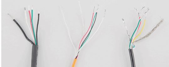
Here we have a large black wire, some loose wires, and foil and loose wires respectively as EMI buffers
In General, each load cell has four strain gauges that are hooked up in a wheatstone bridge formation as shown above.
The four wires coming out from the wheatstone bridge on the load cell are usually:
- Excitation+ (E+) or VCC is red
- Excitation- (E-) or ground is black.
- Output+ (O+), Signal+ (S+)+ or Amplifier+ (A+) is white
- O-, S-, or A- is green or blue
Some load cells might have slight variations in color coding such as blue instead of green or yellow instead of black or white if there are only four wires (meaning no wire used as an EMI buffer). You might have to infer a little from the colors that you have, but in general you will usually see these colors.
If the readings from the HX711 are opposite of what you are expect (for example the values decrease as you increase weight) simply reverse the O+/O- wires.
Once the load cell is is hooked up to the amplifier, you can hook up VDD, VCC, DAT, CLK, and GND to a microcontroller such as a RedBoard or Arduino board.
Note VCC is the analog voltage to power the load cell. VDD is the digital supply voltage used to set the logic level.
PRO TIP: In many cases, you can just short VCC and VDD together. If your microcontroller uses 3.3V logic however, you'll want to connect VCC to 5V and VDD to 3.3V.
Hier haben wir einen großen schwarzen Draht, einige lose Drähte, und Folie und lose Drähte als EMI-Puffer
Im Allgemeinen hat jede Wägezelle vier Dehnungsmessstreifen, die in einer Wheatstone-Brückenbildung wie oben gezeigt eingehängt sind.
Die vier Drähte, die aus der Wheatstone-Brücke der Wägezelle kommen, sind gewöhnlich:
Die Anregung + (E +) oder VCC ist rot
Anregung- (E-) oder Masse ist schwarz.
Ausgang + (O +), Signal + (S +) + oder Verstärker + (A +) ist weiß
O-, S- oder A- grün oder blau ist
Einige Wägezellen können leichte Variationen in der Farbcodierung wie blau statt grün oder gelb statt schwarz oder weiß haben, wenn es nur vier Drähte (dh kein Draht als EMI-Puffer verwendet). Möglicherweise müssen Sie ein wenig von den Farben ableiten, die Sie haben, aber im Allgemeinen sehen Sie normalerweise diese Farben.
Wenn die Messwerte vom HX711 entgegengesetzt sind, was Sie erwarten (z. B. die Werte verringern sich, wenn Sie das Gewicht erhöhen),
kehren Sie einfach die O + / O- Drähte um.
Sobald die Wägezelle an den Verstärker angeschlossen ist, können Sie VDD, VCC, DAT, CLK und GND an einen Mikrocontroller wie einen RedBoard oder eine Arduino-Platine anschließen.
Hinweis VCC ist die analoge Spannung zur Versorgung der Wägezelle. VDD ist die digitale Versorgungsspannung, die verwendet wird, um den Logikpegel einzustellen.
PRO TIPP: In vielen Fällen können Sie nur kurz VCC und VDD zusammen. Wenn Ihr Mikrocontroller 3.3V Logik jedoch verwendet, möchten Sie VCC zu 5V und VDD zu 3.3V anschließen
The example code has DAT and CLK hooked up to pin 3 and 2 respectively, but this is easily changed in the code. Any GPIO pin will work for either. Then VCC and VDD just need to be hooked up to 2.7-5V and GND to ground on your microcontroller.
Der Beispielcode hat DAT und CLK an Pin 3 bzw. 2 angeschlossen, was aber leicht im Code geändert werden kann. Jede GPIO-Pin funktioniert entweder für. Dann VCC und VDD müssen nur bis zu 2,7-5V und GND an Masse auf Ihrem Mikrocontroller angeschlossen werden.
Fritzing diagram of HX711 amplifier connected to a RedBoard
Now, if you would like to set up four single load sensors with our combinator board and amplifier, connect the five pins labeled RED, BLK, WHT, GRN, YLW to the matching pins on the HX711. Next, connect each of the four load sensors to the following pins:
- Red → C
- Black → -
- White → +
Wenn Sie vier einzelne Lastsensoren mit unserer Combinator-Platine und Ihrem Verstärker aufbauen möchten, verbinden Sie die fünf Pins RED, BLK, WHT, GRN, YLW mit den passenden Pins des HX711. Als nächstes verbinden Sie jeden der vier Lastsensoren mit den folgenden Pins:
Rot → C
Schwarz → -
Weiß → +
The combinator board also has room for an 8 pin RJ45 socket, which can be used to connect your project via Ethernet cables for long distance applications.
Another nice thing about our combinator board is that most home scales use four single strain gauge load sensors, so this is a handy board for hacking your own scales at home!
Die Kombinator-Platine bietet außerdem Platz für eine 8-polige RJ45-Buchse, mit deren Hilfe Ihr Projekt über Ethernet-Kabel für Langstreckenanwendungen verbunden werden kann.
Eine weitere schöne Sache über unsere Kombinator-Board ist, dass die meisten Hauswaagen verwenden vier einzelne Dehnungsmeßstreifen Lastsensoren, so ist dies ein handliches Board für Hacking Ihre eigenen Waagen zu Hause!
Hacked home scale’s four load sensors hooked up to our combinator board
Die vier Lastsensoren von Hacked home scale sind an unsere Kombinator-Platine angeschlossen
Example of a single strain gauge, or load sensor. Here RED is the center tap
For load sensors, there isn’t a set color coded standard. Comparing the scale pictured above with the load sensor schematic, while the black wires matched, the red and white wires were swapped. Also, only two of the four sensors used a white wire for the ‘center tap’ of the load sensor, the other two used green. I connected the black wires to “-”, the red to “+”, and the white and green wires to “C”.
To determine how to hook up your single strain gauge load cells to the combinator, measure the resistance between the three wires. You should find a larger resistance (close to double) between a pair. In our example the resistance between red and black was 1.6 kΩ, and the resistance between white/green and red was 800 Ω. Therefore, the center tap to the strain gauge is the white/green wire. The center tap or center pin of your strain gauge connects to the “C” pin on the combinator. The larger resistance wires (red and black in this example) connect to the “+” and “-” pins on the combinator.
The combinator board hooks up the four load sensors in such a way that two resistors in the wheatstone bridge configuration are constant values and the other two are variable in this way:
Beispiel eines einzelnen Dehnungsmessstreifens oder Lastsensors. Hier ist RED der Mittenhahn
Für Lastsensoren gibt es keinen farbcodierten Standard. Beim Vergleich der oben dargestellten Skala mit dem Lastsensorschema wurden die roten und weißen Drähte vertauscht, während die schwarzen Drähte zusammenpassten. Außerdem verwendeten nur zwei der vier Sensoren einen weißen Draht für den "Mittenabgriff" des Lastsensors, die anderen beiden verwendeten grün. Ich verband die schwarzen Drähte mit "-", die roten mit "+" und die weißen und grünen Drähte mit "C".
Um festzustellen, wie Sie Ihre einzelnen Dehnungsmeßstreifen an den Kombinator anschließen, messen Sie den Widerstand zwischen den drei Drähten. Sie sollten einen größeren Widerstand (in der Nähe von Doppel) zwischen einem Paar zu finden. In unserem Beispiel betrug der Widerstand zwischen Rot und Schwarz 1,6 kΩ, der Widerstand zwischen Weiß / Grün und Rot betrug 800 Ω. Daher ist der Mittelabgriff zum Dehnungsmeßstreifen der weiß / grüne Draht. Der Mittelhahn oder der Mittelstift Ihres Dehnungsmessstreifens wird mit dem "C" -Stift des Kombinators verbunden. Die größeren Widerstandsdrähte (rot und schwarz in diesem Beispiel) verbinden sich mit den "+" und "-" Pins am Kombinator.
Die Kombinator-Platine schaltet die vier Lastsensoren so ein, dass zwei Widerstände in der Wheatstone-Brückenkonfiguration konstante Werte sind und die beiden anderen auf diese Weise variabel sind
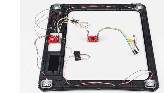
To hook up the combinator board to the HX711 match the RED, BLK, WHT, and GRN pins
Once you have the combinator board successfully soldered to the twelve wires, you can now connect it to the HX711 amplifier board via the 4 standard load cell wires. You can use short jumper wires or if your electronics are a long distance away from your scale consider using an RJ45 connector and an ethernet cable to connect the combinator to the HX711 amplifier.
Zum Verbinden der Combinator-Platine mit dem HX711 passen die ROT-, BLK-, WHT- und GRN-Pins
Sobald Sie das Kombinator-Board erfolgreich an die zwölf Drähte gelötet haben, können Sie es nun über die 4 Standard-Wägezellendrähte an die Verstärkerplatine HX711 anschließen. Sie können kurze Drahtbrücken verwenden, oder wenn Ihre Elektronik weit entfernt von Ihrer Waage ist, sollten Sie einen RJ45-Stecker und ein Ethernet-Kabel verwenden, um den Kombinator mit dem Verstärker HX711 zu verbinden.
Arduino Code
Now that you have your load cell, amplifier, and microcontroller hooked up, you can add your code and start calibrating your setup.
You can download the most up-to-date code and libraries from the link below.
Note: This example assumes you are using the latest version of the Arduino IDE on your desktop. If this is your first time using Arduino, please review our tutorial on installing the Arduino IDE.
If you have not previously installed an Arduino library, please check out our installation guide.
The first thing you will want to work with is the calibration code: “SparkFun_HX711_Calibration”:
Nun, da Sie Ihre Wägezelle, Verstärker und Mikrocontroller angeschlossen haben, können Sie Ihren Code hinzufügen und starten Sie Ihr Setup zu kalibrieren.
Sie können den aktuellsten Code und Bibliotheken aus dem untenstehenden Link herunterladen.
Hinweis: In diesem Beispiel wird davon ausgegangen, dass Sie die neueste Version der Arduino IDE auf Ihrem Desktop verwenden. Wenn dies Ihr erstes Mal mit Arduino ist, lesen Sie bitte unser Tutorial zur Installation der Arduino IDE.
Wenn Sie noch keine Arduino-Bibliothek installiert haben, lesen Sie bitte unsere Installationsanleitung.
Das erste, was Sie wollen, ist der Kalibrierungscode: "SparkFun_HX711_Calibration":
/* Example using the SparkFun HX711 breakout board with a scale By: Nathan Seidle SparkFun Electronics Date: November 19th, 2014 License: This code is public domain but you buy me a beer if you use this and we meet someday (Beerware license). This is the calibration sketch. Use it to determine the calibration_factor that the main example uses. It also outputs the zero_factor useful for projects that have a permanent mass on the scale in between power cycles. Setup your scale and start the sketch WITHOUT a weight on the scale Once readings are displayed place the weight on the scale Press +/- or a/z to adjust the calibration_factor until the output readings match the known weight Use this calibration_factor on the example sketch This example assumes pounds (lbs). If you prefer kilograms, change the Serial.print(" lbs"); line to kg. The calibration factor will be significantly different but it will be linearly related to lbs (1 lbs = 0.453592 kg). Your calibration factor may be very positive or very negative. It all depends on the setup of your scale system and the direction the sensors deflect from zero state This example code uses bogde's excellent library: https://github.com/bogde/HX711 bogde's library is released under a GNU GENERAL PUBLIC LICENSE Arduino pin 2 -> HX711 CLK 3 -> DOUT 5V -> VCC GND -> GND Most any pin on the Arduino Uno will be compatible with DOUT/CLK. The HX711 board can be powered from 2.7V to 5V so the Arduino 5V power should be fine.*/#include "HX711.h"#define DOUT  3#define CLK  2HX711 scale(DOUT, CLK);float calibration_factor = -7050; //-7050 worked for my 440lb max scale setupvoid setup() {  Serial.begin(9600);  Serial.println("HX711 calibration sketch");  Serial.println("Remove all weight from scale");  Serial.println("After readings begin, place known weight on scale");  Serial.println("Press + or a to increase calibration factor");  Serial.println("Press - or z to decrease calibration factor");  scale.set_scale();  scale.tare(); //Reset the scale to 0  long zero_factor = scale.read_average(); //Get a baseline reading  Serial.print("Zero factor: "); //This can be used to remove the need to tare the scale. Useful in permanent scale projects.  Serial.println(zero_factor);}void loop() {  scale.set_scale(calibration_factor); //Adjust to this calibration factor  Serial.print("Reading: ");  Serial.print(scale.get_units(), 1);  Serial.print(" lbs"); //Change this to kg and re-adjust the calibration factor if you follow SI units like a sane person  Serial.print(" calibration_factor: ");  Serial.print(calibration_factor);  Serial.println();  if(Serial.available())  {    char temp = Serial.read();    if(temp == '+' || temp == 'a')      calibration_factor += 10;    else if(temp == '-' || temp == 'z')      calibration_factor -= 10;  }}


Once you have calculated your calibration factor of your load cell set up, you can move on to other code, such as the simple scale output example code, “SparkFun_HX711_Example”:

Sobald Sie den Kalibrierfaktor Ihres Wägezellensatzes berechnet haben
Up, können Sie auf andere Code, wie die einfache Skala Ausgang zu bewegen
Beispielcode "SparkFun_HX711_Example":
/* Example using the SparkFun HX711 breakout board with a scale By: Nathan Seidle SparkFun Electronics Date: November 19th, 2014 License: This code is public domain but you buy me a beer if you use this and we meet someday (Beerware license). This example demonstrates basic scale output. See the calibration sketch to get the calibration_factor for your specific load cell setup. This example code uses bogde's excellent library: https://github.com/bogde/HX711 bogde's library is released under a GNU GENERAL PUBLIC LICENSE The HX711 does one thing well: read load cells. The breakout board is compatible with any wheat-stone bridge based load cell which should allow a user to measure everything from a few grams to tens of tons. Arduino pin 2 -> HX711 CLK 3 -> DAT 5V -> VCC GND -> GND The HX711 board can be powered from 2.7V to 5V so the Arduino 5V power should be fine.*/#include "HX711.h"#define calibration_factor -7050.0 //This value is obtained using the SparkFun_HX711_Calibration sketch#define DOUT 3#define CLK 2HX711 scale(DOUT, CLK);void setup() { Serial.begin(9600); Serial.println("HX711 scale demo"); scale.set_scale(calibration_factor); //This value is obtained by using the SparkFun_HX711_Calibration sketch scale.tare(); //Assuming there is no weight on the scale at start up, reset the scale to 0 Serial.println("Readings:");}void loop() { Serial.print("Reading: "); Serial.print(scale.get_units(), 1); //scale.get_units() returns a float Serial.print(" lbs"); //You can change this to kg but you'll need to refactor the calibration_factor Serial.println();}
Check out the other example code in the Github repo for powering down the HX711 (github) and known zero startup (github).
Resources and Going Further
Want to know more? Check out this tutorial if you haven’t already:
Getting Started with Load Cells
June 11, 2015
A tutorial defining what a load cell is and how to use one.
You may also be interested in learning about the OpenScale.
OpenScale Applications and Hookup Guide
July 22, 2016
OpenScale allows you to have a permanent scale for industrial and biological applications. Learn how to use the OpenScale board to read and configure load cells.
Need even more? Check out this awesome article wheatstone bridges and load cell types.
For some inspiration, check out the SparkFun IoT Beehive:
And stay up to date with the OpenScale by following it on GitHub:
Schauen Sie sich den anderen Beispielcode im Github-Repo an, um den HX711 (github) und den bekannten Null-Start (github) auszuschalten.
Ressourcen und weiter gehen
Möchten Sie mehr wissen? Schauen Sie in diesem Tutorial, wenn Sie noch nicht:
Erste Schritte mit Ladezellen
11. Juni 2015
Ein Tutorial definiert, was eine Wägezelle ist und wie man eins verwendet.
Sie interessieren sich auch für das OpenScale-Lernen.
OpenScale-Anwendungen und Hookup-Handbuch
22. Juli 2016
OpenScale ermöglicht Ihnen eine permanente Skala für industrielle und biologische Anwendungen. Erfahren Sie, wie Sie mit der OpenScale-Karte Wägezellen lesen und konfigurieren können.
Brauchen Sie noch mehr? Überprüfen Sie heraus diese ehrfürchtigen Artikel wheatstone Brücken und Wägezellen-Typen.
Für einige Inspiration, schauen Sie sich die SparkFun IoT Bienenstock:
Das Internet der Bienen: Hinzufügen von Sensoren zu Hive Health zu überwachen
Und halten Sie sich auf dem Laufenden mit dem OpenScale, indem Sie es auf GitHub folgen:
Internet der Bienen GitHub Repository
https://learn.sparkfun.com/tutorials/load-cell-amplifier-hx711-breakout-hookup-guide
DIN A4 ausdrucken
********************************************************I*
Impressum: Fritz Prenninger, Haidestr. 11A, A-4600 Wels, Ober-Österreich, mailto: [email protected]
ENDE
|


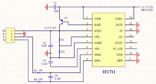
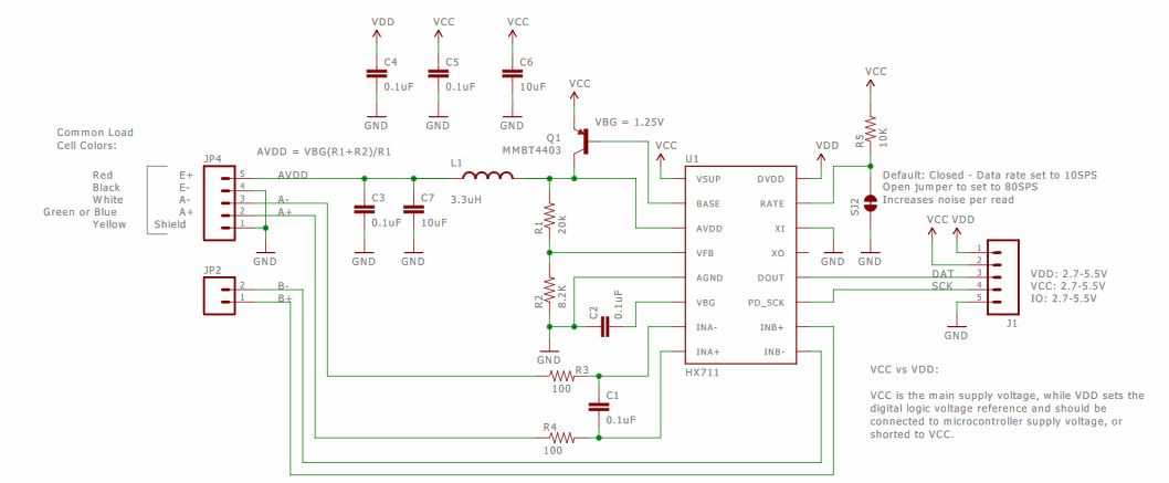

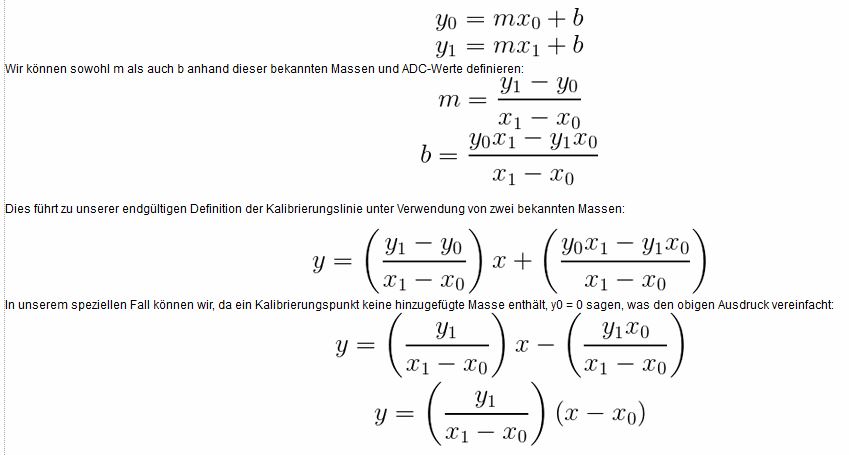

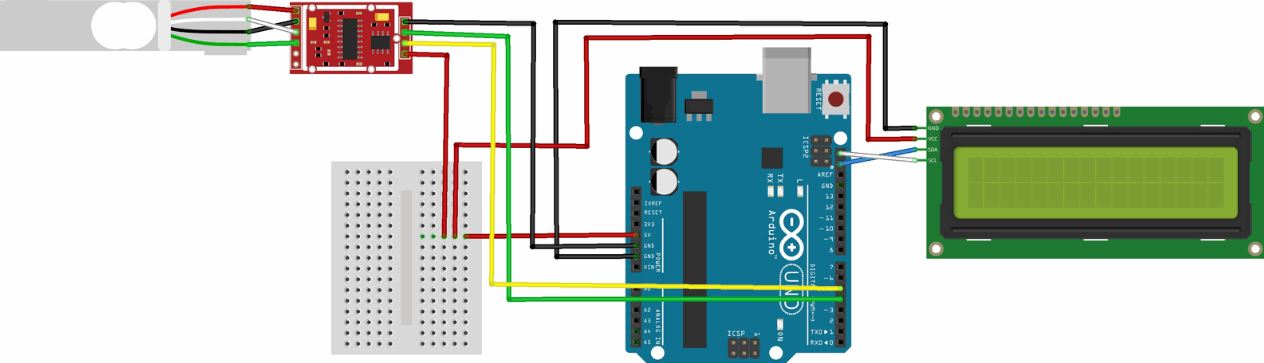

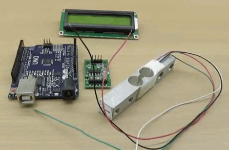
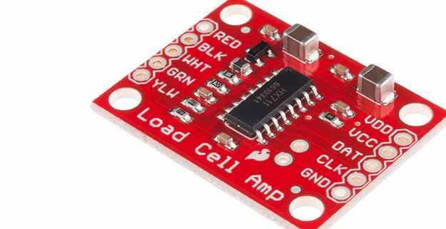
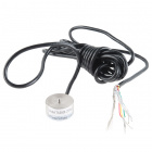
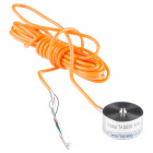
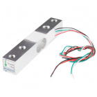
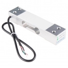
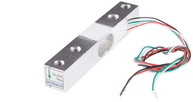
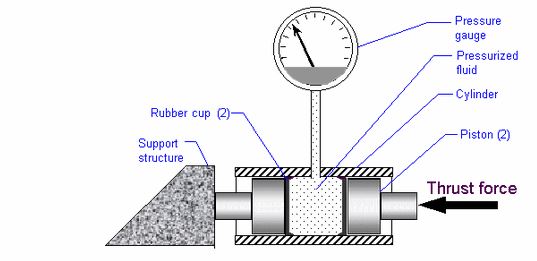


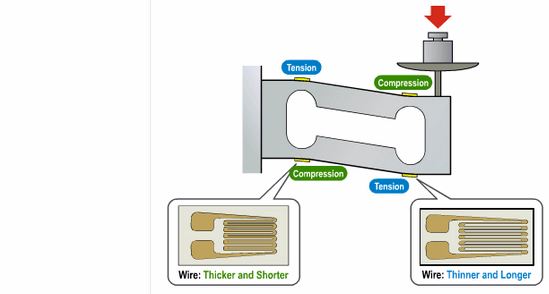


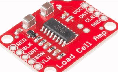
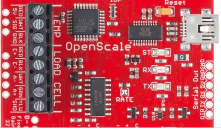

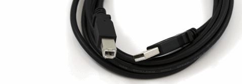

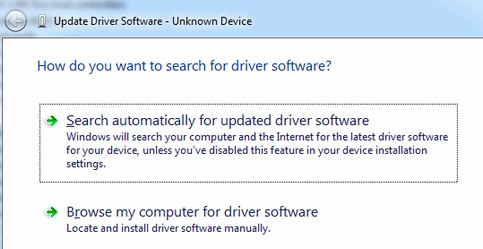

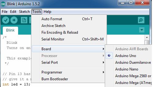


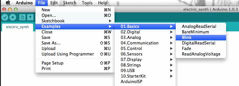


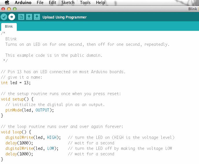


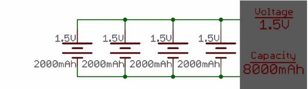
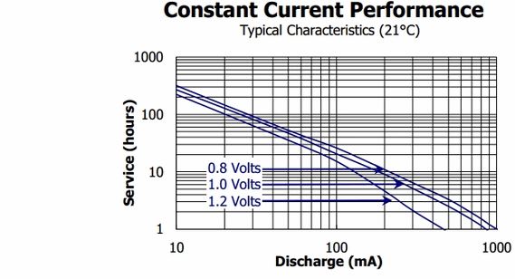


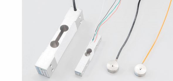

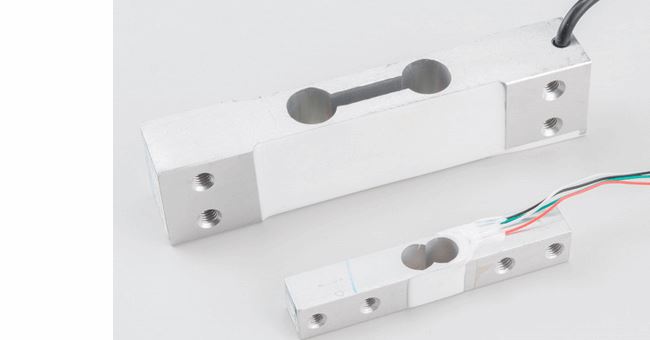

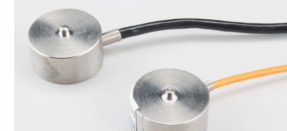
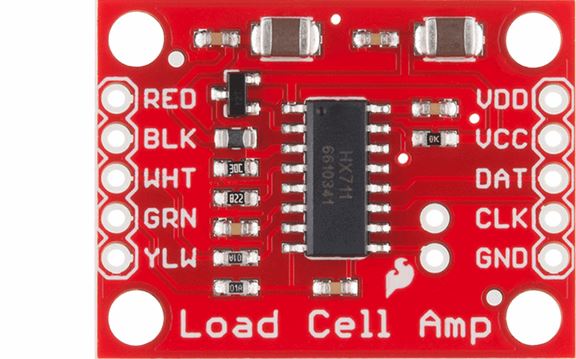

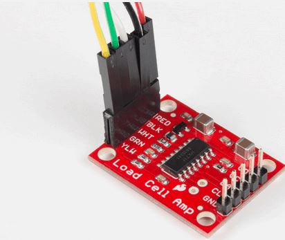
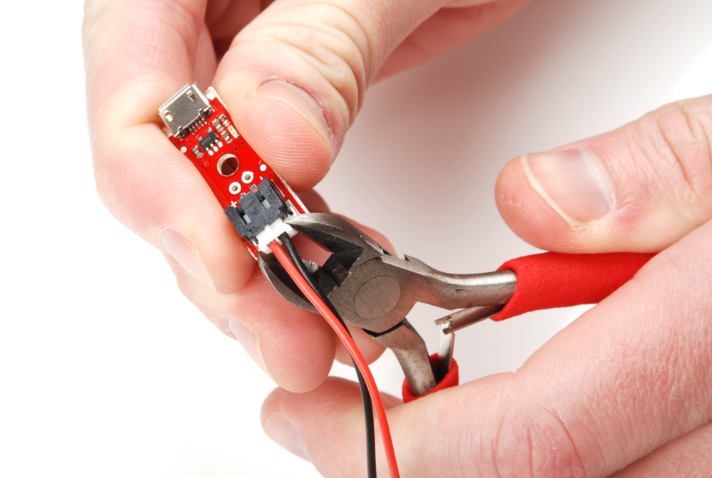


