|
http://sites.schaltungen.at/arduino-uno-r3/sd-card-shield/adafruit-logger-shield
FEHLER in allen Internet-Sketches Wels, am 2014-09-14BITTE nützen Sie doch rechts OBEN das Suchfeld [ ] [ Diese Site durchsuchen]DIN A3 oder DIN A4 quer ausdrucken ********************************************************************************* DIN A4 ausdrucken
*********************************************************
Untergeordnete Seiten (7): SDR-Shield SDR = Digital-Radi
Fritz Prenninger
//int photocellPin = 0; // pin-A0 an CdS = Fotowiderstand LDR//int tempPin = 1; // pin-A1 an TMP36 Temperatur-Sensor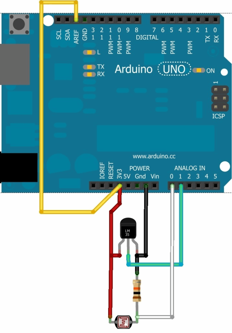
Arduino > SD-SpeicherkartenDatenlogging auf SD-Speicherkarte http://macherzin.net/article47 sd_karte_lesen_schreiben_01.ino http://www.ladyada.net/make/logshield/ http://www.maxpie.de/Data%20Logging%20Shield%20Testmessungen.pdf https://learn.adafruit.com/adafruit-data-logger-shield/light-and-temperature-logger-use-it https://learn.adafruit.com/adafruit-data-logger-shield/light-and-temperature-logger https://learn.adafruit.com/adafruit-data-logger-shield https://github.com/adafruit/Data-Logger-shield/tree/master/pcb/ logger v1.0.brd logger v1.0.sch http://www.ladyada.net/images/logshield/logschemv1.png https://github.com/adafruit/Light-and-Temp-logger lighttemplogger.pde http://www.3helix.rpi.edu/wp-content/uploads/2011/06/duolighttemplogger.txt Adafruit Assembled Data Logging Shield for ArduinoShield (Data Logging) for Arduino
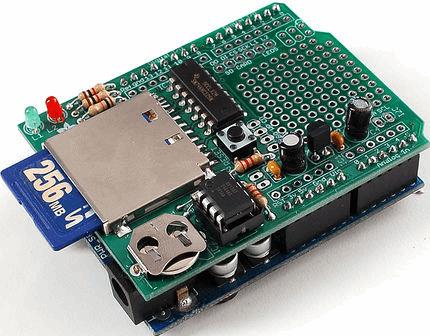
Data logging shield Here's a handy Arduino shield: we've had a lot of people looking for a dedicated and well-designed data logging shield. We worked hard to engineer an inexpensive but well-rounded design. Not only is it easy to assemble and customize, it also comes with great documentation and libraries. You can get going within an hour - saving data to files on any FAT16 or FAT32 formatted SD card, to be read by any plotting, spreadsheet or analysis program. We even have a tutorial on how to use two free software programs to plot your data. The included Real Time Clock timestamps all your data with the current time, so that you know precisely what happened when!
Schritt 1: Overview
This page will run through the schematic, explaining whats going on and why picked the parts we did! Here's the 'big picture' schematic for reference: 
Power supply:

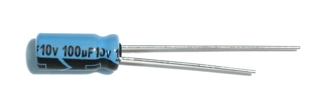
There is a small power supply on the board for generating 3.3V @ 250mA. We don't use the 'built in' 3.3v regulator on the Arduino because its only guaranteed up to 50mA and some SD card need a lot of power when writing. This supply is nice and steady, we can use it as an analog reference too! We have two sets of bypass caps to try and keep both 5V and 3.3V supply nice and clean - the 100uF ones are for the low frequency noise and 0.1 for higher frequency
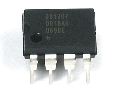
Real Time Clock:

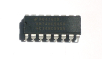
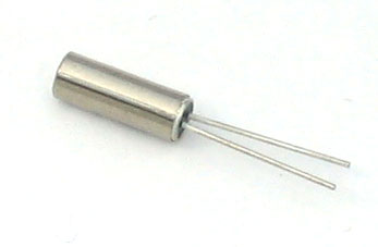
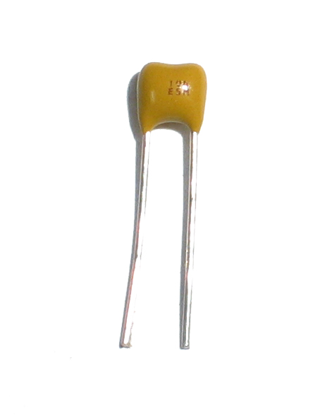
The real time clock is the DS1307 from Maxim, which has a battery backup (CR1220) and communicates with the Arduino via i2c (the SCL and SDA lines). i2c requires pullup resistors on the clock and data lines, which you see as R1 and R2. 2.2K are good values, but if you're in a bind, 1.0K to 10K will probably work fine. The RTC requires a single 12.5pF load crystal at 32.768 KHz, Q1 - this is how it keeps time
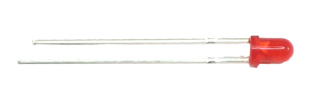
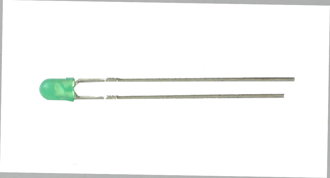
There are also two LEDs for general purpose blinkin' - we like to use them to tell when the SD card is being written to. SD card interface:

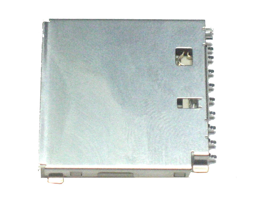
The SD card holder is connected to the Arduino through a buffer IC3. The buffer is a level shifter, converting the 5V signals into 3.3V ones which are safe to use. (For some cards its OK to use 5V signals but you risk the card being permanently damaged!) There is a pull up on the CS line so that if you program the Arduino with a ISP programmer while theres a card in, you wont scramble it. There are two 'unused' lines from the SD card - Card Detect is shorted to ground when a card is inserted. Write Protect is shorted to ground when a card with the safety switch flipped is inserted.
Arduino interface!
Finally we have the arduino interface. The Datalogger shield uses 6 pins. Analog 4 and 5 are the i2c hardware pins. The SD card uses Digital pins 13, 12, 11, and 10. The first three are pretty much required. If you really need pin 10, you can edit the library header file and change it from pin 10 to any other pin. BUT you must have pin 10 as an output, if its an input, the SD interface wont work (its a really annoying thing about AVRs - not sure why this is). A standard 6 pin ISP header is available in case you want to program the Arduino with code using a stand-alone programmer
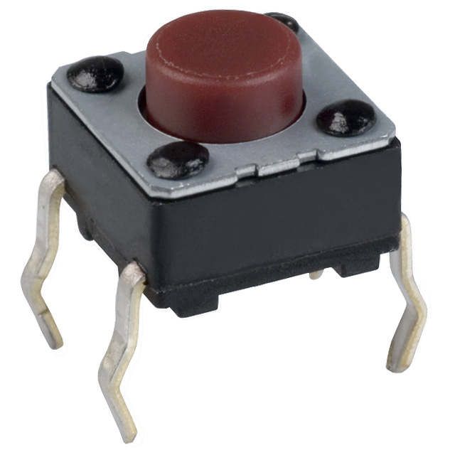
There is also a RESET button, handy when you want to start the Arduino over! Schritt 2: Tools and Preparation
How to:
This kit is pretty simple, but you should follow these steps fully so that you'll have no problems! Learn to solderLearn how to solder with tons of tutorials!
Tools
There are a few tools that are required for assembly. None of these tools are included. If you don't have them, now would be a good time to borrow or purchase them. They are very very handy whenever assembling/fixing/modifying electronic devices! I provide links to buy them, but of course, you should get them wherever is most convenient/inexpensive. Many of these parts are available in a place like Radio Shack or other (higher quality) DIY electronics stores. I recommend a "basic" electronics tool set for this kit, which I describe here.
Schritt 3: Check the Parts ListBill of Materials
Schritt 4: Solder the kit!// - - - - - - - - - - - - - - - - - - - - - - - - -0- - - - - - - - - - - - - - - - - - - - // Titel: GitHub adafruit/Light-and-Temp-logger// Beschreibung: Light-and-Temp-logger / lighttemplogger.pde // Autor: Fritz Prenninger// Datum: 2014-11-11// Sketch: Light_and_Temp_Logger_auf_SD-Card_3a.ino// Shield: Fa. Adafruit "Assembled Data Logging Shield"// Board: ARDUINO UNO Rev3 - ATmega328p// Software: ARDUINO-IDE 1.0.5-r2// Tools: COM5 9.600 Baud// DataLogging_Sensor_Test_CdS_TMP36_Teiler_1e.ino// 123456789012345678901234567890123456789012345678901234567890123456789012345678901234567890// Einfacher Datenlogger - Fa. adafruit Datalogging Arduino Shield// pin-0 "Serial-Monitor" (I2C)// pin-1 "Serial-Monitor" (I2C)// pin-2 Jumper (uberkreuz) auf L2 LED rot (Datenspeicherung alle 60.000ms)// pin-3 Jumper auf L1 LED grün (Messwert einlesen alle 1.000ms)// pin-10 verwendet das adafruit "Data Logging Shield"// pin-Aref=3,3V extern (intern 5,0V pin-Aref n.c. ODER 1,1V pin-Aref n.c.)// pin-A0 LDR (CdS Fotowiderstand)// pin-A1 TMP36 (Temperatur-IC)// pin-A2 3,3V 10k--10k = 1,65V// pin-A3 5,0V 10k--10k = 2,50V// pin-A4 SDA Real Time Clock (I2C) (Adafruit RTC Modul)// pin-A5 SCL Real Time Clock (I2C)// https://github.com/adafruit/Light-and-Temp-logger/blob/master/lighttemplogger// finster 33=33,13Vcc Dämmerung 414=2,71Vcc hell 712 1,58Vcc Sonne 1006 1,12Vcc//// Seit Excel 2007 kann ein Tabellenblatt 1.048.576 Zeilen und 16.384 Spalten (A bis XFD),// also 17.179.869.184 Zellen umfassen. Davor war die Größe 65.536 Zeilen und 256 Spalten // (A bis IV), also 16.777.216 Zellen, begrenzt. Ist in jedem dieser Felder eine Ziffer// eingetragen, so hat eine Datei in Office 2003 eine Größe von 227 MB,// in Office 2013 eine Größe von 1382,4 MB also 1,35 GB.// - - - - - - - - - - - - - - - - - - - - - - - - -1- - - - - - - - - - - - - - - - - - - - #include <Wire.h> // I2C-Libraries einbinden - "Serial-Monitor"#include "RTClib.h" // RTC (Echtzeituhr DS1307) Bibliothek einbinden#include <SD.h> // SD-Card Libraries einbinden (SanDisk 32GB)#define LOG_INTERVAL 3000 // ** alle 1s wird ein Meßwerte eingelesen (LEDgrün)#define SYNC_INTERVAL 6000 // ** alle 60s werden die dann vorh. 60 Meßwerte auf die SD-Karte // geschrieben (LEDrot) wenn die Stromversorgung ausfällt, gehen bis zu 60 Meßwerte verlohrenuint32_t syncTime = 0; // Zeit der letzten Synchronisierung ()#define ECHO_TO_SERIAL 1 // Daten auch an den "Serial-Monitor" senden//#define ECHO_TO_SERIAL 0 // Daten nicht an den "Serial-Monitor" senden#define WAIT_TO_START 0 // Nicht warten auf Zeichen-Eingabe im "Serial-Monitor"//#define WAIT_TO_START 1 // Warten auf Zeichen-Eingabe im "Serial-Monitor" #define redLEDpin 2 // LED rot blinkt auf beim Speichern (Dauer-rot Karte fehlt)#define greenLEDpin 3 // LED grün (Lesen/Schreiben von Meßdaten)//int photocellPin = 0; // pin-A0 an CdS = Fotowiderstand//int tempPin = 1; // pin-A1 an TMP36 Temperatur-Sensor#define photocellPin 0 // pin-A0 an CdS = Fotowiderstand#define tempPin 1 // pin-A1 an TMP36 Temperatur-Sensor#define teilerPin 2 // pin-A2 Teiler 10k--10k 3,3V/2 = 1,65V = 500..512//#define Aref_voltage 5.0 // analogReference(DEFAULT) pin-Aref muß n.c. sein#define Aref_voltage 3.301 // analogReference(EXTERNAL) pin-Aref an 3,301V//#define Aref_voltage 1.1 // analogReference(INTERNAL) pin-Aref muß n.c. sein#define Bandgap_voltage 1.1 // Geheim-Kanal-14 1,10V Referenz// - - - - - - - - - - - - - - - - - - - - - - - - -2- - - - - - - - - - - - - - - - - - - - RTC_DS1307 RTC; // Den Real-Time-Clock IC initialisieren// Das Fa. Adafruit "Data Logging Shield", verwendet den pin-10 für die SD-Card CS-Leitung// Das ARDUINO "Ethernet Shield", verwendet den pin-D4 für die SD-Card ChipSelect-Leitungconst int chipSelect = 10; // pin-10 auf Ausgang, auch wenn Loggin-Shield diesen nicht benutzenFile logfile; // die Logging-Datei// Fehlerfunktion void error(char *str) soll implementiert werden, die einen String entgegen nimmtvoid error(char *str) { Serial.print("FEHLER: "); Serial.println(str); // (println beendet die Zeile) digitalWrite(redLEDpin, HIGH); // leuchten der rote LED zeigt Fehler an (keine SD-Karte steckt) while(1); // Endlosschleife = Stillstand bei Fehler}// - - - - - - - - - - - - - - - - - - Geheimkanal 14 - - - - - - - - - - - - - - - - - - - // aus der internen 1,1V Ref.Sp. hochgerechnete auf Vcclong readVcc() { long result; // 1,1V lesen Referenz gegen AVcc ADMUX = _BV(REFS0) | _BV(MUX3) | _BV(MUX2) | _BV(MUX1); delay(2); // 2ms warten bis Vref lesebereit ADCSRA |= _BV(ADSC); // konvertieren while (bit_is_set(ADCSRA,ADSC)); result = ADCL; result |= ADCH<<8; result = 1250000L / result; // int.-Ref 1,25V auf AVcc (50000mV) hoch gerechnet return result;}// - - - - - - - - - - - - - - - - - - - - - - - - -3- - - - - - - - - - - - - - - - - - - - void setup(void) // Ser. Ausgabe starten, warten auf Zeichen-Eingabe im "Serial-Monitor"{ Serial.begin(9600); // "Serial-Monitor" mit 9.600 Baud initialisieren (möglich 1200..115200) Serial.println(); // println beendet die Zeile // die rote und grüne LED zeigen auch FEHLER an pinMode(redLEDpin, OUTPUT); // FEHLER oder Datenspeicherung pin-2 auf Ausgang pinMode(greenLEDpin, OUTPUT); // Meßwert-Erfassung pin-3 auf Ausgang#if WAIT_TO_START Serial.println("einen beliebiges Zeichen in den Serial Monitor eingeben um Prg. zu starten"); while (!Serial.available());#endif //WAIT_TO_START Serial.println("Initialisiere SD-Card: "); // SD-Card initialisieren, prüfen ob FAT32 formatiert // Sicher stellen daß der Standard-Chip-Select pin gesetzt ist (pin-D10 bei Data Logging Shield) pinMode(chipSelect, OUTPUT); // pin-10 auf Ausgang, auch wenn Loggin-Shield diesen nicht benutzen // nachsehen, ob die Karte vorhanden ist und initialisiert werden kann. if (!SD.begin(chipSelect)) { error("SD-Karte hat einen Fehler oder ist nicht gesteckt"); // FEHLER: rote LED leuchtet } Serial.println("SD-Karte wurde initialisiert"); // Eine neue Messdaten-Datei (comma-separated-value Datei) erstellen. char filename[] = "LOGGER00.CSV"; //SD-Karten File-Name mit EXCEL-Extension *.CSV Format for (uint8_t i = 0; i < 100; i++) { // max. 99 Files möglich dann kommt Fehlermeldung filename[6] = i/10 + '0'; filename[7] = i%10 + '0'; if (! SD.exists(filename)) { // Es öffnet Sie eine neue Datei, wenn sie nicht vorhanden ist logfile = SD.open(filename, FILE_WRITE); break; // verlasse die Schleife! } } if (! logfile) { error("konnte die Datei nicht erstellen"); } Serial.print("*.csv Daten-File: "); Serial.println(filename); // (println beendet die Zeile) Wire.begin(); // Echtzeit-Uhr DS1307 verbinden if (!RTC.begin()) { logfile.println("RTC fehlgeschlagen");#if ECHO_TO_SERIAL // schreib auch in den "Serial-Monitor" wenn ECHO_TO_SERIAL 1 ist (bei 0 nicht) Serial.println("RTC fehlgeschlagen");#endif //ECHO_TO_SERIAL } logfile.println("milliS;Date;Time;Licht;Temp;Teiler;Vcc"); // EXCEL-File mit Semikolon getrennt (;)#if ECHO_TO_SERIAL // Versuch in die Datei zu schreiben Serial.println("milliS, UnixZeit, JJJJ-MM-TT HH:MM:SS <Roh> Grad-C ~ Licht ~ Teiler, Vcc"); //RTC.adjust(DateTime(2014, 8, 8, 23, 1, 0));#endif //ECHO_TO_SERIAL //analogReference(DEFAULT); // pin-Aref muß n.c. sein Vcc +5,0V ist Referenz analogReference(EXTERNAL); // ** bei an pin-Aref ext. angelegte Spannung von +3,3V //analogReference(INTERNAL); // pin-Aref muß n.c. sein - interne 1,1V Referenz}// - - - - - - - - - - - - - - - - - - - - - - - - -4- - - - - - - - - - - - - - - - - - - - void loop(void){ DateTime now; // Verzögerungs-Zeit, zwischen den Messungen (siehe LOG_INTERVALL 6000) delay((LOG_INTERVAL -1) - (millis() % LOG_INTERVAL)); digitalWrite(greenLEDpin, HIGH); // grüne LED ein, bei jeder Messung uint32_t m = millis(); // Anmelden der Zeit seit Arduino gestartet ist logfile.print(m); // speichert die milliSekunden die seit dem Start vergangen sind logfile.print("; "); // *.csv EXCEL-Trennzeichen das Semikolon (;)#if ECHO_TO_SERIAL Serial.print(m); // schreibt Millisekunden die seit dem Start vergangen sind Serial.print(", ");#endif// - - - - - - - - - - - - - - - - - - - - - - - - -5- - - - - - - - - - - - - - - - - - - - now = RTC.now(); // hole aktuelles Datum/Zeit von der Echzeit-Uhr und speichere auf die SD-Card //logfile.print(now.unixtime()); // UnixZeit Sekunden seit 1.1.1970 //logfile.print("; "); // Zeitformat das von EXCEL erkannt werden kann 2014-09-14 23:01:59 logfile.print('"'); logfile.print(now.year(), DEC); logfile.print("-"); logfile.print(now.month(), DEC); logfile.print("-"); logfile.print(now.day(), DEC); logfile.print(";"); logfile.print(now.hour(), DEC); logfile.print(":"); logfile.print(now.minute(), DEC); logfile.print(":"); logfile.print(now.second(), DEC); logfile.print('"');#if ECHO_TO_SERIAL // hole aktuelles Datum/Zeit von RTC und sende zum "Serial-Monitor" Serial.print(now.unixtime()); // UnixZeit Sekunden seit 1.1.1970 Serial.print(", "); Serial.print(" D "); Serial.print(now.year(), DEC); Serial.print("-"); Serial.print(now.month(), DEC); Serial.print("-"); Serial.print(now.day(), DEC); Serial.print(" "); Serial.print(now.hour(), DEC); Serial.print(":"); Serial.print(now.minute(), DEC); Serial.print(":"); Serial.print(now.second(), DEC); Serial.print(" h ");#endif //ECHO_TO_SERIAL// - - - - - - - - - - - - - - - - - - - - - - - - -6- - - - - - - - - - - - - - - - - - - - analogRead(photocellPin); // pin-A0 Fotowiderstand delay(10); // 10ms Wartezeit um Lesart zu wechseln int photocellReading = analogRead(photocellPin); analogRead(tempPin); // pin-A1 Temperatur-IC TMP36 delay(10); // 10ms Wartezeit um Lesart zu wechseln int tempReading = analogRead(tempPin); analogRead(teilerPin); // pin-A2 Spannungsteiler 1,65V Wert 510..512 delay(10); // 10ms Wartezeit um Lesart zu wechseln int teilerReading = analogRead(teilerPin); // Analoge ReferenzSpannung - RohWert-Umwandlung, bei 3,301V Referenz-Spannung float voltage = tempReading * Aref_voltage / 1023; // Umwandlung rohDaten bezogen auf pin-Aref float temperatureC = (voltage - 0.5) * 100 ; // TMP36 Umwandlung 10mV/gradC mit 0,5V Offset //float temperatureF = (temperatureC * 9 / 5) + 32; // in Fahrenheit konvertieren logfile.print("; "); logfile.print(photocellReading); // Licht-Wert 0..1024 auf SD-Card speichern logfile.print("; "); logfile.print(temperatureC); // Temperatur-Wert in °C auf SD-Card speichern // logfile.print(temperatureF); // Temperatur-Wert speichern in Fahrenheit logfile.print("; "); logfile.print(teilerReading); // pin-A2 Spannungsteiler 1,65V Wert 510..512 #if ECHO_TO_SERIAL //sendet Daten als ASCII-Zeichen an die serielle Schnittstelle Serial.print(" <"); Serial.print(tempReading); // Temp Roh-Werte zum "Serial-Monitor" senden Serial.print("> "); Serial.print(temperatureC); // Grad Celsius zum "Serial-Monitor" senden // Serial.print(temperatureF); // Fahrenheit Grade zum "Serial-Monitor" senden Serial.print("C ~ "); Serial.print(photocellReading); // Licht-Wert 0..1023 zum "Serial-Monitor" senden Serial.print(" ~ "); Serial.print(teilerReading); // pin-A2 Spannungsteiler 1,65V Wert 510..512#endif //ECHO_TO_SERIAL// - - - - - - - - - - - - - - - - - - - - - - - - -7- - - - - - - - - - - - - - - - - - - - logfile.print("; "); //logfile.print(supplyvoltage); logfile.print( readVcc(), DEC ); #if ECHO_TO_SERIAL //Serial.print(supplyvoltage); Serial.print(" Vcc="); Serial.print( readVcc(), DEC ); // aus der internen 1,1V Ref.Sp. hochgerechnete auf Vcc Serial.print("mV");#endif // ECHO_TO_SERIAL logfile.println(); // println beendet die Zeile#if ECHO_TO_SERIAL Serial.println(); // println beendet die Zeile#endif // ECHO_TO_SERIAL// - - - - - - - - - - - - - - - - - - - - - - - - -8- - - - - - - - - - - - - - - - - - - - digitalWrite(greenLEDpin, LOW); //grüne LED aus // die Daten werden auf die microSD-Speicherkarte geschrieben // die erste Speicherung allerr Werte nach 60sec if ((millis() - syncTime) < SYNC_INTERVAL) return; // SYNC_INTERVAL = 60.000 syncTime = millis(); // rote LED blinkt auf, um das Schreiben der Daten und die Aktualisierung der FAT anzuzeigen ! digitalWrite(redLEDpin, HIGH); logfile.flush(); // leert den Empfangsbuffer der seriellen Schnittstelle digitalWrite(redLEDpin, LOW);}// - - - - - - - - - - - - - - - - - - - - - - - - -9- - - - - - - - - - - - - - - - - - - - // adafruit Light-and-Temp-logger / lighttemplogger.pde #define BANDGAPREF 14 analogRead(BANDGAPREF); da der Geheimkanal 14 mit analogRead(14) nicht gelesen werden kann
analogRead(14) ist nähmlich ident mit analogRead(0)
Ich als Anfänger muß auf diesen Fehler draufkommen.
Kopieren da alle ohne jemals etwas zu testen.
http://www.3helix.rpi.edu/wp-content/uploads/2011/06/duolighttemplogger.txt #include <SD.h>#include <Wire.h>#include "RTClib.h"// A simple data logger for the Arduino analog pins// Based on the lighttemplogger code developed by LadyAda// how many milliseconds between grabbing data and logging it. 1000 ms is once a second#define LOG_INTERVAL 1000 // mills between entries (reduce to take more/faster data)// how many milliseconds before writing the logged data permanently to disk// set it to the LOG_INTERVAL to write each time (safest)// set it to 10*LOG_INTERVAL to write all data every 10 datareads, you could lose up to // the last 10 reads if power is lost but it uses less power and is much faster!#define SYNC_INTERVAL 10000 // mills between calls to flush() - to write data to the carduint32_t syncTime = 0; // time of last sync()#define ECHO_TO_SERIAL 1 // echo data to serial port#define WAIT_TO_START 0 // Wait for serial input in setup()// the digital pins that connect to the LEDs#define redLEDpin 2#define greenLEDpin 3// The analog pins that connect to the sensors#define photocellPin1 0 // analog 0#define tempPin1 1 // analog 1#define photocellPin2 2 // analog 2#define tempPin2 3 // analog 3#define BANDGAPREF 14 // special indicator that we want to measure the bandgap#define aref_voltage 3.3 // we tie 3.3V to ARef and measure it with a multimeter!#define bandgap_voltage 1.1 // this is not super guaranteed but its not -too- offRTC_DS1307 RTC; // define the Real Time Clock object// for the data logging shield, we use digital pin 10 for the SD cs lineconst int chipSelect = 10;// the logging fileFile logfile;void error(char *str){ Serial.print("error: "); Serial.println(str); // red LED indicates error digitalWrite(redLEDpin, HIGH); while(1);}void setup(void){ Serial.begin(115200); Serial.println(); // use debugging LEDs pinMode(redLEDpin, OUTPUT); pinMode(greenLEDpin, OUTPUT); #if WAIT_TO_START Serial.println("Type any character to start"); while (!Serial.available());#endif //WAIT_TO_START // initialize the SD card Serial.print("Initializing SD card..."); // make sure that the default chip select pin is set to // output, even if you don't use it: pinMode(10, OUTPUT); // see if the card is present and can be initialized: if (!SD.begin(chipSelect)) { error("Card failed, or not present"); } Serial.println("card initialized."); // create a new file char filename[] = "LOGGER00.CSV"; for (uint8_t i = 0; i < 100; i++) { filename[6] = i/10 + '0'; filename[7] = i%10 + '0'; if (! SD.exists(filename)) { // only open a new file if it doesn't exist logfile = SD.open(filename, FILE_WRITE); break; // leave the loop! } } if (! logfile) { error("couldnt create file"); } Serial.print("Logging to: "); Serial.println(filename); // connect to RTC Wire.begin(); if (!RTC.begin()) { logfile.println("RTC failed");#if ECHO_TO_SERIAL Serial.println("RTC failed");#endif //ECHO_TO_SERIAL } logfile.println("millis,stamp,datetime,light1,temp1,light2,temp2,vcc"); #if ECHO_TO_SERIAL Serial.println("millis,stamp,datetime,light1,temp1,light2,temp2,vcc");#endif //ECHO_TO_SERIAL // If you want to set the aref to something other than 5v analogReference(EXTERNAL);}void loop(void){ DateTime now; // delay for the amount of time we want between readings delay((LOG_INTERVAL -1) - (millis() % LOG_INTERVAL)); digitalWrite(greenLEDpin, HIGH); // log milliseconds since starting uint32_t m = millis(); logfile.print(m); // milliseconds since start logfile.print(", "); #if ECHO_TO_SERIAL Serial.print(m); // milliseconds since start Serial.print(", "); #endif // fetch the time now = RTC.now(); // log time logfile.print(now.unixtime()); // seconds since 1/1/1970 logfile.print(", "); logfile.print('"'); logfile.print(now.year(), DEC); logfile.print("/"); logfile.print(now.month(), DEC); logfile.print("/"); logfile.print(now.day(), DEC); logfile.print(" "); logfile.print(now.hour(), DEC); logfile.print(":"); logfile.print(now.minute(), DEC); logfile.print(":"); logfile.print(now.second(), DEC); logfile.print('"');#if ECHO_TO_SERIAL Serial.print(now.unixtime()); // seconds since 1/1/1970 Serial.print(", "); Serial.print('"'); Serial.print(now.year(), DEC); Serial.print("/"); Serial.print(now.month(), DEC); Serial.print("/"); Serial.print(now.day(), DEC); Serial.print(" "); Serial.print(now.hour(), DEC); Serial.print(":"); Serial.print(now.minute(), DEC); Serial.print(":"); Serial.print(now.second(), DEC); Serial.print('"');#endif //ECHO_TO_SERIAL analogRead(photocellPin1); delay(10); int photocellReading1 = analogRead(photocellPin1); analogRead(tempPin1); delay(10); int tempReading1 = analogRead(tempPin1); // converting that reading to voltage, for 3.3v arduino use 3.3, for 5.0, use 5.0 float voltage1 = tempReading1 * aref_voltage / 1024; float temperatureC1 = (voltage1 - 0.5) * 100 ; analogRead(photocellPin2); delay(10); int photocellReading2 = analogRead(photocellPin2); analogRead(tempPin2); delay(10); int tempReading2 = analogRead(tempPin2); // converting that reading to voltage, for 3.3v arduino use 3.3, for 5.0, use 5.0 float voltage2 = tempReading2 * aref_voltage / 1024; float temperatureC2 = (voltage2 - 0.5) * 100 ; logfile.print(", "); logfile.print(photocellReading1); logfile.print(", "); logfile.print(temperatureC1); logfile.print(", "); logfile.print(photocellReading2); logfile.print(", "); logfile.print(temperatureC2);#if ECHO_TO_SERIAL Serial.print(", "); Serial.print(photocellReading1); Serial.print(", "); Serial.print(temperatureC1); Serial.print(", "); Serial.print(photocellReading2); Serial.print(", "); Serial.print(temperatureC2);#endif //ECHO_TO_SERIAL // Log the estimated 'VCC' voltage by measuring the internal 1.1v ref analogRead(BANDGAPREF); delay(10); int refReading = analogRead(BANDGAPREF); float supplyvoltage = (bandgap_voltage * 1024) / refReading; logfile.print(", "); logfile.print(supplyvoltage);#if ECHO_TO_SERIAL Serial.print(", "); Serial.print(supplyvoltage);#endif // ECHO_TO_SERIAL logfile.println();#if ECHO_TO_SERIAL Serial.println();#endif // ECHO_TO_SERIAL digitalWrite(greenLEDpin, LOW); // Now we write data to disk! Don't sync too often - requires 2048 bytes of I/O to SD card // which uses a bunch of power and takes time if ((millis() - syncTime) < SYNC_INTERVAL) return; syncTime = millis(); // blink LED to show we are syncing data to the card & updating FAT! digitalWrite(redLEDpin, HIGH); logfile.flush(); digitalWrite(redLEDpin, LOW); }http://www.3helix.rpi.edu/wp-content/uploads/2011/06/duolighttemplogger.txt DIN A4 ausdrucken ********************************************************* Impressum: Fritz Prenninger, Haidestr. 11A, A-4600 Wels, Ober-Österreich, mailto:[email protected] ENDE |
SD-Card-Shield >