|
http://sites.schaltungen.at/arduino-uno-r3/keyestudio
DIN A3 oder DIN A4 quer ausdrucken ~015_b_PrennIng-a_arduino.uno.r3-keyestudio (xx Seiten)_1a.pdf
*******************************************************************************I** DIN A4 ausdrucken siehe********************************************************I*
ks0069 (72,73) keyestudio basic starter kit for uno and mega.pdf - Google Drive.html
303_d_arduino-x_keyestudio Basic Starter Kit for Arduino UNO - Tutorial engl. (109 Seiten)_1a.pdf
keyestudio Basic Starter Kit for arduino Starter with UNO R3 $ 29,99
with ARDUINO UNO R3
Ks0069(72, 73) keyestudio Basic Starter Kit for Arduino Starters
01. Hello World
02. LED Blinking 03. PWM 04. Traffic Light 05. LED Chase Effect 06. Button-controlled LED 07. Active Buzzer 08. Passive Buzzer 09. RGB LED 10. Photo Resistor 11. Flame Sensor 12. LM35 Temperature Sensor 13. Tilt Switch 14. IR Remote Control 15. Analog Value Reading 16. 74HC595 17. 1-digit LED Segment Display 18. 4-digit LED Segment Display 19. 8x8 LED Matrix 20. 1602 LCD 21. 9g Servo Control
keyestudio Basic Starter Kit for UNO and Mega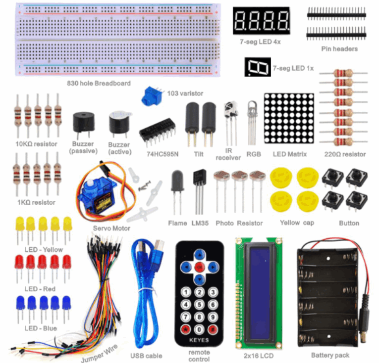
1. Kit Introduction
This is the basic Starter Kit, developed specially for those beginners who are interested in Arduino. You will have a set of Arduino's most common and useful electronic components. What's more. We will offer you a detailed tutorials including project introduction and their source codes.You may learn about Arduino through using these basic projects. This kit will help you control the physical world with sensors. Dies ist das grundlegende Starter-Kit, das speziell für Anfänger entwickelt wurde, die sich für Arduino interessieren. Sie werden eine Reihe von Arduinos häufigsten und nützlichsten elektronischen Komponenten haben. Was ist mehr. Wir werden Ihnen detaillierte Tutorials mit Projekteinführung und deren Quellcodes anbieten. Sie können sich mit diesen grundlegenden Projekten über Arduino informieren. Mit diesem Kit können Sie die physische Welt mit Sensoren steuern.

2.Kit Contents
Kit A for ARDUINO UNO R3
Kit B for Mega2560 R3
Kit C Without board
ARDUINO UNO R3 UNO R3 5x LED - blue 5x LED - red 5x LED - yellow 1x LED - RGB 5x 10k resistor 5x 1k resistor 8x 220R resistor 1x 10K Potentiometer 1x 7-seg LED 1x module 1x 7-seg LED 4x module 1x 8x8 LED Matrix 1x Buzzer active 1x Buzzer passive = Lautsprecher 1x Flame sensor 1x IR receiver 1x IR remote control 1x LM35 Temp Sensor 2x Ball tilt sensor 3x Photo Resistor 4x Small button switch 1x IC 74HC595N 16-pin DIP 1x LCD1602 1x 9g Servo 1x BreadBoard 830-pin 10x Dupont connector wires 1x AA Battery pack 6-cell 1x USB cable a 3. Project List
1. Hello World 4. Project DetailsProject 1: Hello WorldIntroduction: As for starters, we will begin with something simple. In this project, you only need an Arduino and a USB cable to start the "Hello World!" experiment. This is a communication test of your Arduino and PC, also a primer project for you to have your first try of the Arduino world! Zunächst einmal beginnen wir mit etwas Einfachem. In diesem Projekt benötigen Sie nur ein Arduino und ein USB-Kabel, um die "Hallo Welt!" Experiment. Dies ist ein Kommunikationstest von Ihrem Arduino und PC, auch ein Grundlegendes Projekt für Sie, um Ihren ersten Versuch der Arduino Welt zu machen!
Hardware Required:
Sample Code: Nachdem wir den Treiber für Arduino installiert haben, öffnen wir die Arduino-Software und kompilieren den Code, mit dem Arduino "Hello World!" unter deiner Anleitung. Natürlich können Sie Code für Arduino kompilieren, um "Hallo Welt!" ohne Anleitung. Eine einfache If () Anweisung wird den Befehlstrick ausführen. Wenn die Onboard-LED an Pin 13 angeschlossen ist, können wir die LED anweisen, zuerst zu blinken, wenn Arduino eine Anweisung erhält und dann "Hello World!" int val;//define variable valint ledpin=13;// define digital interface 13void setup(){ Serial.begin(9600);// set the baud rate at 9600 to match the software set up. When connected to a specific device, (e.g. bluetooth), the baud rate needs to be the same with it. pinMode(ledpin,OUTPUT);// initialize digital pin 13 as output. When using I/O ports on an Arduino, this kind of set up is always needed.}void loop(){ val=Serial.read();// read the instruction or character from PC to Arduino, and assign them to Val. if(val=='R')// determine if the instruction or character received is “R”. { // if it’s “R”, digitalWrite(ledpin,HIGH);// set the LED on digital pin 13 on. delay(500);digitalWrite(ledpin,LOW);// set the LED on digital pin 13 off. delay(500); Serial.println("Hello World!");// display“Hello World!”string.}
Result: 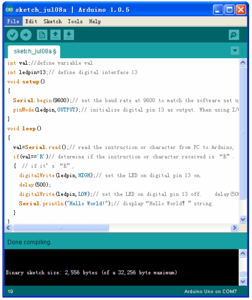
Click serial port monitor

After you choose the right port, the experiment should be easy for you! Project 2: LED BlinkingIntroduction: Blinking LED experiment is quite simple. In the "Hello World!" program, we have come across LED. This time, we are going to connect an LED to one of the digital pins rather than using LED13, which is soldered to the board. Except an Arduino and an USB cable, we will need extra parts as below: Blinkendes LED-Experiment ist ziemlich einfach. In der "Hallo Welt!" Programm haben wir auf LED gestoßen. Dieses Mal werden wir eine LED an einen der digitalen Pins anschließen, anstatt die LED13 zu verwenden, die an die Platine gelötet ist. Außer einem Arduino und einem USB-Kabel benötigen wir zusätzliche Teile wie folgt:
Hardware Required: We follow below diagram from the experimental schematic link. Here we use digital pin 10. We connect LED to a 220 ohm resistor to avoid high current damaging the LED. Wir folgen unten Diagramm von der experimentellen schematischen Verbindung. Hier verwenden wir den digitalen Pin 10. Wir verbinden die LED mit einem 220 Ohm Widerstand, um einen hohen Strom zu vermeiden, der die LED beschädigt. Connection for UNO R3: 
Connection for Mega 2560 R3: 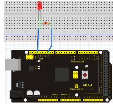
Sample Code: int ledPin = 10; // define digital pin 10.void setup(){pinMode(ledPin, OUTPUT);// define pin with LED connected as output.}void loop(){digitalWrite(ledPin, HIGH); // set the LED on.delay(1000); // wait for a second.digitalWrite(ledPin, LOW); // set the LED off.delay(1000); // wait for a second}
Result: Nach dem Herunterladen dieses Programms sehen Sie im Experiment die mit Pin 10 verbundene LED mit einem Intervall von etwa einer Sekunde. Das blinkende LED-Experiment ist jetzt abgeschlossen. Vielen Dank! Project 3: PWMIntroduction: PWM, short for Pulse Width Modulation, is a technique used to encode analog signal level into digital ones. A computer cannot output analog voltage but only digital voltage values such as 0V or 5V. So we use a high resolution counter to encode a specific analog signal level by modulating the duty cycle of PMW. The PWM signal is also digitalized because in any given moment, fully on DC power supply is either 5V (ON), or 0V (OFF). The voltage or current is fed to the analog load (the device that uses the power) by repeated pulse sequence being ON or OFF. Being on, the current is fed to the load; being off, it's not. With adequate bandwidth, any analog value can be encoded using PWM. The output voltage value is calculated via the on and off time. Output voltage = (turn on time/pulse time) * maximum voltage value PWM, kurz für Pulsweitenmodulation, ist eine Technik, die verwendet wird, um analoge Signalpegel in digitale zu codieren. Ein Computer kann keine analoge Spannung, sondern nur digitale Spannungswerte wie 0 V oder 5 V ausgeben. Daher verwenden wir einen Zähler mit hoher Auflösung, um einen spezifischen analogen Signalpegel zu codieren, indem das Tastverhältnis von PMW moduliert wird. Das PWM-Signal wird auch digitalisiert, weil zu jedem beliebigen Zeitpunkt die DC-Stromversorgung entweder 5 V (ON) oder 0 V (OFF) ist. Die Spannung oder der Strom wird der analogen Last (dem Gerät, das die Leistung verwendet) zugeführt, indem die wiederholte Impulsfolge EIN oder AUS ist. Angeschaltet wird der Strom der Last zugeführt; weg sein, ist es nicht. Bei ausreichender Bandbreite kann jeder Analogwert mit PWM codiert werden. Der Wert der Ausgangsspannung wird über die Ein- und Ausschaltzeit berechnet. Ausgangsspannung = (Einschaltzeit / Impulszeit) * maximaler Spannungswert 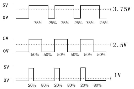
PWM has many applications: lamp brightness regulating, motor speed regulating, sound making, etc.The following are the three basic parameters of PMW:

1. The amplitude of pulse width (minimum / maximum) 2. The pulse period (The reciprocal of pulse frequency in 1 second) 3. The voltage level(such as:0V..5V) There are 6 PMW interfaces on Arduino, namely digital pin 3, 5, 6, 9, 10, and 11. In previous experiments, we have done "button-controlled LED", using digital signal to control digital pin, also one about potentiometer. This time, we will use a potentiometer to control the brightness of the LED. Hardware Required: 1. Potentiometer 10k 2. Red Dm=5mm LED 3. 220Ω resistor 4. Breadboard 5. BreadBoard jumper wires*several
The input of potentiometer is analog, so we connect it to analog port, and LED to PWM port. Different PWM signal can regulate the brightness of the LED.

Sample Code: Bei der Programmkompilierung verwenden wir die Funktion analogWrite (PWM-Schnittstelle, Analogwert). In diesem Experiment werden wir den Analogwert des Potentiometers lesen und den Wert dem PWM-Port zuweisen, so dass sich die Helligkeit der LED entsprechend ändert. Ein letzter Teil zeigt den analogen Wert auf dem Bildschirm an. Sie können dies als das Projekt "Analogwert-Lesen" betrachten, das den PWM-Analogwert-Zuordnungsteil hinzufügt. Unten ist ein Beispielprogramm für Ihre Referenz. int potpin=0;// initialize analog pin 0int ledpin=11;//initialize digital pin 11(PWM output)int val=0;// Temporarily store variables' value from the sensorvoid setup(){pinMode(ledpin,OUTPUT);// define digital pin 11 as “output”Serial.begin(9600);// set baud rate at 9600// attention: for analog ports, they are automatically set up as “input”}void loop(){val=analogRead(potpin);// read the analog value from the sensor and assign it to valSerial.println(val);// display value of valanalogWrite(ledpin,val/4);// turn on LED and set up brightness(maximum output of PWM is 255)delay(10);// wait for 0.01 second}
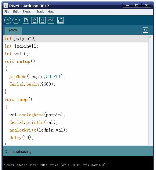
Result: After downloading the program, when we rotate the potentiometer knob, we can see changes of the displaying value, also obvious change of the LED brightness on the breadboard. Project 4: Traffic LightIntroduction:
In the previous program, we have done the LED blinking experiment with one LED. Now, it’s time to up the stakes and do a bit more complicated experiment-traffic lights. Actually, these two experiments are similar. While in this traffic lights experiment, we use 3 LEDs with different color other than 1 LED.
Hardware Required: Connection for UNO R3:

Sample Code: int redled =10; // initialize digital pin 8.int yellowled =7; // initialize digital pin 7.int greenled =4; // initialize digital pin 4.void setup(){pinMode(redled, OUTPUT);// set the pin with red LED as “output”pinMode(yellowled, OUTPUT); // set the pin with yellow LED as “output”pinMode(greenled, OUTPUT); // set the pin with green LED as “output”}void loop(){digitalWrite(greenled, HIGH);//// turn on green LEDdelay(5000);// wait 5 secondsdigitalWrite(greenled, LOW); // turn off green LEDfor(int i=0;i<3;i++)// blinks for 3 times{delay(500);// wait 0.5 seconddigitalWrite(yellowled, HIGH);// turn on yellow LEDdelay(500);// wait 0.5 seconddigitalWrite(yellowled, LOW);// turn off yellow LED} delay(500);// wait 0.5 seconddigitalWrite(redled, HIGH);// turn on red LEDdelay(5000);// wait 5 seconddigitalWrite(redled, LOW);// turn off red LED}
Result: Project 5: LED Chasing EffectIntroduction:
We often see billboards composed of colorful LEDs. They are constantly changing to form various effects. In this experiment, we compile a program to simulate chase effect.
Hardware Required: Connection for UNO R3: 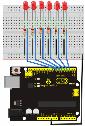
Sample Code: int BASE = 2 ; // the I/O pin for the first LEDint NUM = 6; // number of LEDsvoid setup(){ for (int i = BASE; i < BASE + NUM; i ++) { pinMode(i, OUTPUT); // set I/O pins as output }}void loop(){ for (int i = BASE; i < BASE + NUM; i ++) { digitalWrite(i, LOW); // set I/O pins as “low”, turn off LEDs one by one. delay(200); // delay } for (int i = BASE; i < BASE + NUM; i ++) { digitalWrite(i, HIGH); // set I/O pins as “high”, turn on LEDs one by one delay(200); // delay}
Result: Project 6: Button-controlled LEDIntroduction:
I/O port means interface for INPUT and OUTPUT. Up until now, we have only used its OUTPUT function. In this experiment, we will try to use the input function, which is to read the output value of device connecting to it. We use 1 button and 1 LED using both input and output to give you a better understanding of the I/O function. Button switches, familiar to most of us, are a switch value (digital value) component. When it's pressed, the circuit is in closed (conducting) state.
Hardware Required: Connection for UNO R3: 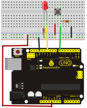
Sample Code: int ledpin=11;// initialize pin 11int inpin=7;// initialize pin 7int val;// define valvoid setup(){pinMode(ledpin,OUTPUT);// set LED pin as “output”pinMode(inpin,INPUT);// set button pin as “input”}void loop(){val=digitalRead(inpin);// read the level value of pin 7 and assign if to valif(val==LOW)// check if the button is pressed, if yes, turn on the LED{ digitalWrite(ledpin,LOW);}else{ digitalWrite(ledpin,HIGH);}}
Result: Project 7: Active BuzzerIntroduction:
Active buzzer is widely used on computer, printer, alarm, electronic toy, telephone, timer etc as a sound making element. It has an inner vibration source. Simply connect it with 5V power supply, it can buzz continuously.
Hardware Required: Connection for UNO R3: 
Connection for ARDUINO Mega 2560 R3:
Sample Code: int buzzer=8;// initialize digital IO pin that controls the buzzervoid setup() { pinMode(buzzer,OUTPUT);// set pin mode as “output”} void loop() {digitalWrite(buzzer, HIGH); // produce sound}
Result: Project 8: Passive BuzzerIntroduction:
We can use Arduino to make many interactive works of which the most commonly used is acoustic-optic display. All the previous experiment has something to do with LED. However, the circuit in this experiment can produce sound. Normally, the experiment is done with a buzzer or a speaker while buzzer is simpler and easier to use. The buzzer we introduced here is a passive buzzer. It cannot be actuated by itself, but by external pulse frequencies. Different frequencies produce different sounds. We can use Arduino to code the melody of a song, which is actually quite fun and simple. Wir können Arduino verwenden, um viele interaktive Arbeiten zu machen, von denen das am häufigsten verwendete akustisch-optische Display ist. Alles vorherige Experiment hat etwas mit LED zu tun. Die Schaltung in diesem Experiment kann jedoch Schall erzeugen. Normalerweise wird das Experiment mit einem Summer oder einem Lautsprecher durchgeführt, während der Summer einfacher und einfacher zu verwenden ist. Der Summer, den wir hier eingeführt haben, ist ein passiver Summer. Es kann nicht von selbst, sondern von externen Pulsfrequenzen ausgelöst werden. Unterschiedliche Frequenzen erzeugen unterschiedliche Töne. Wir können Arduino verwenden, um die Melodie eines Liedes zu kodieren, was eigentlich ziemlich lustig und einfach ist.
Hardware Required: Connection for UNO R3: 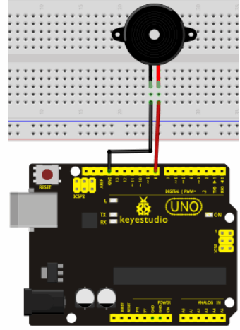
Sample Code: int buzzer=8;// select digital IO pin for the buzzervoid setup() { pinMode(buzzer,OUTPUT);// set digital IO pin pattern, OUTPUT to be output } void loop() { unsigned char i,j;//define variablewhile(1) { for(i=0;i<80;i++)// output a frequency sound{ digitalWrite(buzzer,HIGH);// sounddelay(1);//delay1ms digitalWrite(buzzer,LOW);//not sounddelay(1);//ms delay } for(i=0;i<100;i++)// output a frequency sound{ digitalWrite(buzzer,HIGH);// sounddigitalWrite(buzzer,LOW);//not sounddelay(2);//2ms delay }
Result: Project 9: RGB LEDIntroduction:
Tricolor principle to display various colors
Hardware Required: Connection for UNO R3: 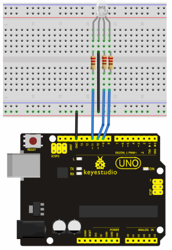
Sample Code: int redpin = 11; //select the pin for the red LEDint bluepin =10; // select the pin for the blue LEDint greenpin =9;// select the pin for the green LEDint val;void setup() { pinMode(redpin, OUTPUT); pinMode(bluepin, OUTPUT); pinMode(greenpin, OUTPUT); Serial.begin(9600);}void loop() {for(val=255; val>0; val--) { analogWrite(11, val); analogWrite(10, 255-val); analogWrite(9, 128-val); delay(1); }for(val=0; val<255; val++) { analogWrite(11, val); analogWrite(10, 255-val); analogWrite(9, 128-val); delay(1); } Serial.println(val, DEC);}
Result: Project 10: Photo ResistorIntroduction:
After completing all the previous experiments, we acquired some basic understanding and knowledge about Arduino application. We have learned digital input and output, analog input and PWM. Now, we can begin the learning of sensors applications.
Nach Abschluss aller vorherigen Experimente haben wir ein grundlegendes Verständnis und Wissen über die Arduino-Anwendung erworben. Wir haben digitale Ein- und Ausgänge, analoge Eingänge und PWM gelernt. Jetzt können wir mit dem Lernen von Sensoranwendungen beginnen.
Hardware Required: Connection for UNO R3: 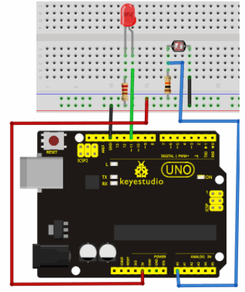
Sample Code: int potpin=0;// initialize analog pin 0, connected with photovaristorint ledpin=11;// initialize digital pin 11, output regulating the brightness of LEDint val=0;// initialize variable vavoid setup(){pinMode(ledpin,OUTPUT);// set digital pin 11 as “output”Serial.begin(9600);// set baud rate at “9600”}void loop(){val=analogRead(potpin);// read the analog value of the sensor and assign it to valSerial.println(val);// display the value of valanalogWrite(ledpin,val);// turn on the LED and set up brightness(maximum output value 255)delay(10);// wait for 0.01}
Result: Project 11: Flame SensorIntroduction:
Flame sensor (Infrared receiving triode) is specially used on robots to find the fire source. This sensor is of high sensitivity to flame. Below is a photo of it. 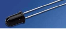
Working Principle:
Sensor Connection: 
Hardware Required:
Experiment connection:
2)Connecting flame sensor: Connection for UNO R3:

Experiment principle: Wenn es sich einem Feuer nähert, unterscheidet sich der Spannungswert, den der analoge Port liest. Wenn Sie ein Multimeter verwenden, können Sie wissen, wenn sich kein Feuer nähert, die Spannung, die es liest, ist ungefähr 0.3V; Wenn sich Feuer nähert, beträgt die gemessene Spannung ungefähr 1,0 V, je näher das Feuer ist, desto höher ist die Spannung. Zu Beginn des Programms können Sie den Spannungswert i initialisieren (kein Feuerwert); Dann lese kontinuierlich den analogen Spannungswert j und erhalte den Differenzwert k = j-i; vergleiche k mit 0,6V (123 in binär), um festzustellen, ob sich ein Feuer nähert oder nicht; wenn ja, wird der Summer summen.
Sample Code: int flame=0;// select analog pin 0 for the sensor int Beep=9;// select digital pin 9 for the buzzer int val=0;// initialize variable void setup() { pinMode(Beep,OUTPUT);// set LED pin as “output” pinMode(flame,INPUT);// set buzzer pin as “input” Serial.begin(9600);// set baud rate at “9600” } void loop() { val=analogRead(flame);// read the analog value of the sensor Serial.println(val);// output and display the analog value if(val>=600)// when the analog value is larger than 600, the buzzer will buzz { digitalWrite(Beep,HIGH); }else { digitalWrite(Beep,LOW); } delay(500); }
Result: Project 12: LM35 Temperature SensorIntroduction: LM35 is a common and easy-to-use temperature sensor. It does not require other hardware. You just need an analog port to make it work. The difficulty lies in compiling the code to convert the analog value it reads to celsius temperature.
Hardware Required: Connection for UNO R3: 
int potPin = 0; // initialize analog pin 0 for LM35 temperature sensorvoid setup(){Serial.begin(9600);// set baud rate at”9600”}void loop(){int val;// define variableint dat;// define variableval=analogRead(0);// read the analog value of the sensor and assign it to valdat=(125*val)>>8;// temperature calculation formulaSerial.print("Tep:");// output and display characters beginning with TepSerial.print(dat);// output and display value of datSerial.println("C");// display “C” charactersdelay(500);// wait for 0.5 second}
Result:

Project 13: Tilt SwitchIntroduction: Tilt switch controlling the ON and OFF of LED
Hardware Required: Connection for UNO R3: 
Connect the controller board, shield, breadboard and USB cable according to Arduino tutorial. Connect the LED to digital pin 8, ball switch to analog pin 5. Experiment Principle:When one end of the switch is below horizontal position, the switch is on. The voltage of the analog port is about 5V (1023 in binary). The LED will be on. When the other end of the switch is below horizontal position, the switch is off. The voltage of the analog port is about 0V (0 in binary). The LED will be off. In the program, we determine whether the switch is on or off according to the voltage value of the analog port, whether it's above 2.5V (512 in binary) or not.
Verbinden Sie die Controller-Platine, den Shield, das Steckbrett und das USB-Kabel gemäß dem Arduino-Lernprogramm. Verbinden Sie die LED mit dem digitalen Pin 8, den Ballschalter mit dem analogen Pin 5.
Sample Code: void setup() { pinMode(8,OUTPUT);// set digital pin 8 as “output” } void loop() { int i;// define variable i while(1) { i=analogRead(5);// read the voltage value of analog pin 5 if(i>512)// if larger that 512(2.5V) { digitalWrite(8,LOW);// turn on LED } else// otherwise { digitalWrite(8,HIGH);// turn off LED }
Result: Project 14: IR Remote ControlIntroduction:
What is an infrared receiver?
Was ist ein Infrarotempfänger?
Working Principal:
Der eingebaute Empfänger wandelt das vom Sender empfangene Lichtsignal in ein schwaches elektrisches Signal um. Das Signal wird vom IC-Verstärker verstärkt. Nach automatischer Verstärkungsregelung, Bandpassfilterung, Demodulation, Waveshaping kehrt es zum ursprünglichen Code zurück. Der Code wird dann durch den Signalausgangsstift des Empfängers in die Code-Identifikationsschaltung eingegeben. Der Pin und die Verbindung des Infrarot-Empfangskopfes. 
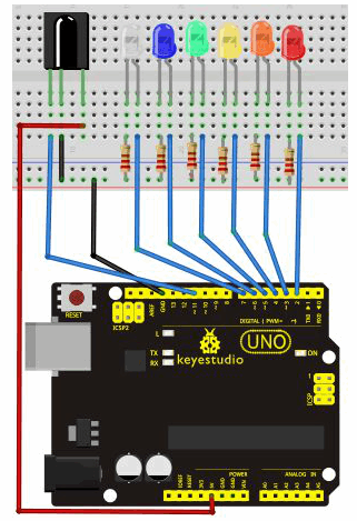
Infrared receiver has 3 pins. When you use it, connect VOUT to analog pin, GND to GND, VCC to +5V.2. Infrared remote control experiment
Hardware Required: Connection: First, connect the controller board; then connect the infrared receiver as the above mentioned, connect VOUT to digital pin 11, connect the LEDs with resistors and connect the resisters to pin 2,3,4,5,6,7. Connection for UNO R3:
Experimental Principle:If you want to decode code of a remote controller, you must first know how it's coded. The coding method we use here is NEC protocol. Below is a brief introduction.·NEC protocol:
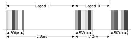
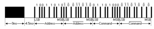
The picture above shows a typical pulse train of the NEC protocol. With this protocol the LSB is transmitted first. In this case Address $59 and Command $16 is transmitted. A message is started by a 9ms AGC burst, which was used to set the gain of the earlier IR receivers. This AGC burst is then followed by a 4.5ms space, which is then followed by the address and command. Address and Command are transmitted twice. The second time all bits are inverted and can be used for verification of the received message. The total transmission time is constant because every bit is repeated with its inverted length. If you are not interested in this reliability, you can ignore the inverted values, or you can expend the Address and Command to 16 bits each! Das Bild oben zeigt eine typische Impulsfolge des NEC-Protokolls. Bei diesem Protokoll wird das LSB zuerst übertragen. In diesem Fall wird Adresse $ 59 und Befehl $ 16 übertragen. Eine Nachricht wird durch einen 9 ms AGC-Burst gestartet, der verwendet wurde, um die Verstärkung der früheren IR-Empfänger einzustellen. Diesem AGC-Burst folgt dann ein 4,5ms-Space, dem die Adresse und der Befehl folgen. Adresse und Befehl werden zweimal gesendet. Beim zweiten Mal werden alle Bits invertiert und können zur Verifizierung der empfangenen Nachricht verwendet werden. Die gesamte Übertragungszeit ist konstant, da jedes Bit mit seiner invertierten Länge wiederholt wird. Wenn Sie nicht an dieser Zuverlässigkeit interessiert sind, können Sie die invertierten Werte ignorieren, oder Sie können die Adresse und den Befehl auf jeweils 16 Bit aufbringen!
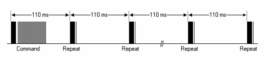
A command is transmitted only once, even when the key on the remote control remains pressed. Every 110ms a repeat code is transmitted for as long as the key remains down. This repeat code is simply a 9ms AGC pulse followed by a 2.25ms space and a 560µs burst.

Note: when the pulse enters the integrated receiver, there will be decoding, signal amplifying and wave shaping process. So you need to make sure the level of the output is just the opposite from that of the signal sending end. That is when there is no infrared signal, the output end is in high level; when there is infrared signal, the output end is in low level. You can see the pulse of the receiving end in the oscilloscope. Try to better understand the program base on what you see. Hinweis: Wenn der Impuls in den integrierten Empfänger eintritt, wird der Prozess der Dekodierung, Signalverstärkung und Wellenformung ausgeführt. Sie müssen also sicherstellen, dass der Pegel des Ausgangs genau das Gegenteil von dem des sendenden Signals ist. Das heißt, wenn kein Infrarotsignal vorliegt, ist das Ausgangsende auf hohem Pegel; Wenn ein Infrarotsignal vorhanden ist, befindet sich das Ausgangsende auf einem niedrigen Pegel. Sie können den Impuls des Empfangsendes im Oszilloskop sehen. Versuchen Sie, die Programmbasis besser zu verstehen, was Sie sehen
Sample Code: #include <IRremote.h>int RECV_PIN = 11;int LED1 = 2;int LED2 = 3;int LED3 = 4;int LED4 = 5;int LED5 = 6;int LED6 = 7;long on1 = 0x00FFA25D;long off1 = 0x00FFE01F;long on2 = 0x00FF629D;long off2 = 0x00FFA857;long on3 = 0x00FFE21D;long off3 = 0x00FF906F;long on4 = 0x00FF22DD;long off4 = 0x00FF6897;long on5 = 0x00FF02FD;long off5 = 0x00FF9867;long on6 = 0x00FFC23D;long off6 = 0x00FFB047;IRrecv irrecv(RECV_PIN);decode_results results;// Dumps out the decode_results structure.// Call this after IRrecv::decode()// void * to work around compiler issue//void dump(void *v) {// decode_results *results = (decode_results *)vvoid dump(decode_results *results) { int count = results->rawlen; if (results->decode_type == UNKNOWN) { Serial.println("Could not decode message"); } else { if (results->decode_type == NEC) { Serial.print("Decoded NEC: "); } else if (results->decode_type == SONY) { Serial.print("Decoded SONY: "); } else if (results->decode_type == RC5) { Serial.print("Decoded RC5: "); } else if (results->decode_type == RC6) { Serial.print("Decoded RC6: "); } Serial.print(results->value, HEX); Serial.print(" ("); Serial.print(results->bits, DEC); Serial.println(" bits)"); } Serial.print("Raw ("); Serial.print(count, DEC); Serial.print("): "); for (int i = 0; i < count; i++) { if ((i % 2) == 1) { Serial.print(results->rawbuf[i]*USECPERTICK, DEC); } else { Serial.print(-(int)results->rawbuf[i]*USECPERTICK, DEC); } Serial.print(" "); } Serial.println(""); }void setup() { pinMode(RECV_PIN, INPUT); pinMode(LED1, OUTPUT); pinMode(LED2, OUTPUT); pinMode(LED3, OUTPUT); pinMode(LED4, OUTPUT); pinMode(LED5, OUTPUT); pinMode(LED6, OUTPUT); pinMode(13, OUTPUT); Serial.begin(9600); irrecv.enableIRIn(); // Start the receiver }int on = 0;unsigned long last = millis();void loop() { if (irrecv.decode(&results)) { // If it's been at least 1/4 second since the last // IR received, toggle the relay if (millis() - last > 250) { on = !on;// digitalWrite(8, on ? HIGH : LOW); digitalWrite(13, on ? HIGH : LOW); dump(&results); } if (results.value == on1 ) digitalWrite(LED1, HIGH); if (results.value == off1 ) digitalWrite(LED1, LOW); if (results.value == on2 ) digitalWrite(LED2, HIGH); if (results.value == off2 ) digitalWrite(LED2, LOW); if (results.value == on3 ) digitalWrite(LED3, HIGH); if (results.value == off3 ) digitalWrite(LED3, LOW); if (results.value == on4 ) digitalWrite(LED4, HIGH); if (results.value == off4 ) digitalWrite(LED4, LOW); if (results.value == on5 ) digitalWrite(LED5, HIGH); if (results.value == off5 ) digitalWrite(LED5, LOW); if (results.value == on6 ) digitalWrite(LED6, HIGH); if (results.value == off6 ) digitalWrite(LED6, LOW); last = millis(); irrecv.resume(); // Receive the next value}
Program Function Decode the coded pulse signal emitted by the remote controller; execute corresponding action according to the results of the decoding. In this way, you will be able to control your device with remote controller.
Result: 
Note:add IRremote folder into installation directory \Arduino\compiler libraries, or you will not be able to compile.For example:C:\Program Files\Arduino\libraries Project 15: Analog Value ReadingIntroduction:
In this experiment, we will begin the learning of analog I/O interfaces. On an Arduino, there are 6 analog interfaces numbered from 0 to 5. These 6 interfaces can also be used as digital ones numbered as 14-19. After a brief introduction, let's begin our project. Potentiometer used here is a typical output component of analog value that is familiar to us.
Hardware Required:
Connection: Connection for UNO R3:
We use the analog interface 0.The analog interface we use here is interface 0.
Sample Code:
The program compiling is simple. An analogRead () Statement can read the value of the interface. The A/D acquisition of Arduino 328 is in 10 bits, so the value it reads is among 0 to 1023. One difficulty in this project is to display the value on the screen, which is actually easy to learn. First, we need to set the baud rate in voidsetup (). Displaying the value is a communication between Arduino and PC, so the baud rate of the Arduino should match the the one in the PC's software set up. Otherwise, the display will be messy codes or no display at all. In the lower right corner of the Arduino software monitor window, there is a button for baud rate set up. The set up here needs to match the one in the program. The statement in the program is Serial.begin(); enclosed is the baud rate value, followed by statement for displaying. You can either use Serial.print() or Serial.println() statement. Das Programm-Compiling ist einfach. Eine analogRead () Anweisung kann den Wert der Schnittstelle lesen. Die A / D-Erfassung von Arduino 328 erfolgt in 10 Bit, der von 0 bis 1023 gelesene Wert. Eine Schwierigkeit in diesem Projekt ist es, den Wert auf dem Bildschirm anzuzeigen, der tatsächlich leicht zu erlernen ist. Zuerst müssen wir die Baudrate in voidsetup () einstellen. Bei der Anzeige des Wertes handelt es sich um eine Kommunikation zwischen Arduino und PC, daher sollte die Baudrate des Arduino mit der in der PC-Software eingestellten übereinstimmen. Andernfalls wird das Display unordentlich oder gar nicht angezeigt. In der unteren rechten Ecke des Arduino Software Monitor-Fensters befindet sich eine Schaltfläche für die Baudrate. Die Einrichtung hier muss mit der im Programm übereinstimmen. Die Anweisung im Programm lautet Serial.begin (); Beigefügt ist der Wert der Baudrate, gefolgt von einer Anweisung für die Anzeige. Sie können entweder die Anweisung Serial.print () oder Serial.println () verwenden. int potpin=0;// initialize analog pin 0int ledpin=13;// initialize digital pin 13int val=0;// define val, assign initial value 0void setup(){pinMode(ledpin,OUTPUT);// set digital pin as “output”Serial.begin(9600);// set baud rate at 9600}void loop(){digitalWrite(ledpin,HIGH);// turn on the LED on pin 13delay(50);// wait for 0.05 seconddigitalWrite(ledpin,LOW);// turn off the LED on pin 13delay(50);// wait for 0.05 secondval=analogRead(potpin);// read the analog value of analog pin 0, and assign it to val Serial.println(val);// display val’s value}
Result:

When you rotate the potentiometer knob, you can see the displayed value changes. The reading of analog value is a very common function since most sensors output analog value. After calculation, we can have the corresponding value we need.The experiment is now completed, thank you. Project 16: 74HC595Introduction:
To put it simply, 74HC595 is a combination of 8-digit shifting register, memorizer and equipped with tri-state output. Here, we use it to control 8 LEDs. You may wonder why use a 74HC595 to control LED? Well, think about how many I/O it takes for an Arduino to control 8 LEDs? Yes, 8. For an Arduino 168, it has only 20 I/O including analog ports. So, to save port resources, we use 74HC595 to reduce the number of ports it needs. Using 74HC595 enables us to use 3 digital I/O port to control 8 LEDs! Um es einfach auszudrücken, 74HC595 ist eine Kombination aus 8-stelligen Shifting-Register, Memorizer und ausgestattet mit Tri-State-Ausgang. Hier steuern wir 8 LEDs. Sie fragen sich vielleicht, warum Sie einen 74HC595 zur Steuerung von LEDs verwenden? Denken Sie darüber nach, wie viele I / O es für einen Arduino benötigt, um 8 LEDs zu steuern? Ja, 8. Für einen Arduino 168 hat er nur 20 E / A einschließlich Analogports. Um Port-Ressourcen zu sparen, verwenden wir 74HC595, um die Anzahl der benötigten Ports zu reduzieren. Mit 74HC595 können wir 3 digitale I / O-Ports zur Steuerung von 8 LEDs verwenden!
Hardware Required: Connection for UNO R3: 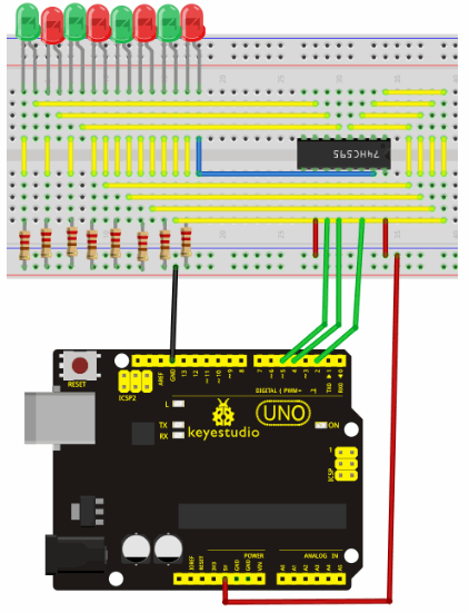
The circuit may seem complicated, but once you give it a good look, you will find it easy!
Sample Code: int data = 2;// set pin 14 of 74HC595as data input pin SI int clock = 5;// set pin 11 of 74hc595 as clock pin SCKint latch = 4;// set pin 12 of 74hc595 as output latch RCK int ledState = 0;const int ON = HIGH;const int OFF = LOW;void setup(){pinMode(data, OUTPUT);pinMode(clock, OUTPUT);pinMode(latch, OUTPUT);}void loop(){for(int i = 0; i < 256; i++){updateLEDs(i);delay(500);}
Result: Project 17: 1-digit LED Segment DisplayIntroduction:
LED segment displays are common for displaying numerical information. It's widely applied on displays of electromagnetic oven, full automatic washing machine, water temperature display, electronic clock etc. It is necessary that we learn how it works.
LED-Segmentanzeigen sind üblich zum Anzeigen von numerischen Informationen. Es ist weit verbreitet auf Anzeigen von elektromagnetischen Ofen, vollautomatische Waschmaschine, Wassertemperaturanzeige, elektronische Uhr usw. Es ist notwendig, dass wir lernen, wie es funktioniert. 
Common anode 7-segment display
Each segment of the display consists of an LED. So when you use it, you also need use a current-limiting resistor. Otherwise, LED will be burnt out. In this experiment, we use a common cathode display. As we mentioned above, for common cathode display, connect the common cathode (COM) to GND. When the anode level of a certain segment is high, the segment is on; when the anode level of a certain segment is low, the segment is off. Jedes Segment des Displays besteht aus einer LED. Wenn Sie es verwenden, müssen Sie auch einen Strombegrenzungswiderstand verwenden. Andernfalls wird die LED durchgebrannt. In diesem Experiment verwenden wir ein gemeinsames Kathoden-Display. Wie oben erwähnt, verbinden Sie für die gemeinsame Kathodenanzeige die gemeinsame Kathode (COM) mit GND. Wenn der Anodenpegel eines bestimmten Segments hoch ist, ist das Segment eingeschaltet; Wenn der Anodenpegel eines bestimmten Segments niedrig ist, ist das Segment ausgeschaltet.
Hardware Required:
Connection : Connection for UNO R3: 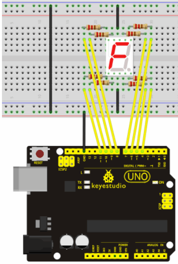
Sample Code: There are seven segments for numerical display, one for decimal point display. Corresponding segments will be turned on when displaying certain numbers. For example, when displaying number 1, b and c segments will be turned on. We compile a subprogram for each number, and compile the main program to display one number every 2 seconds, cycling display number 0 ~ 9. The displaying time for each number is subject to the delay time, the longer the delay time, the longer the displaying time. // set the IO pin for each segmentint a=7;// set digital pin 7 for segment aint b=6;// set digital pin 6 for segment bint c=5;// set digital pin 5 for segment cint d=10;// set digital pin 10 for segment dint e=11;// set digital pin 11 for segment eint f=8;// set digital pin 8 for segment fint g=9;// set digital pin 9 for segment gint dp=4;// set digital pin 4 for segment dpvoid digital_0(void) // display number 5{unsigned char j;digitalWrite(a,HIGH);digitalWrite(b,HIGH);digitalWrite(c,HIGH);digitalWrite(d,HIGH);digitalWrite(e,HIGH);digitalWrite(f,HIGH);digitalWrite(g,LOW);digitalWrite(dp,LOW);}void digital_1(void) // display number 1{unsigned char j;digitalWrite(c,HIGH);// set level as “high” for pin 5, turn on segment cdigitalWrite(b,HIGH);// turn on segment bfor(j=7;j<=11;j++)// turn off other segmentsdigitalWrite(j,LOW);digitalWrite(dp,LOW);// turn off segment dp}void digital_2(void) // display number 2{unsigned char j;digitalWrite(b,HIGH);digitalWrite(a,HIGH);for(j=9;j<=11;j++)digitalWrite(j,HIGH);digitalWrite(dp,LOW);digitalWrite(c,LOW);digitalWrite(f,LOW);}void digital_3(void) // display number 3{digitalWrite(g,HIGH);digitalWrite(a,HIGH);digitalWrite(b,HIGH);digitalWrite(c,HIGH);digitalWrite(d,HIGH);digitalWrite(dp,LOW);digitalWrite(f,LOW);digitalWrite(e,LOW);}void digital_4(void) // display number 4{digitalWrite(c,HIGH);digitalWrite(b,HIGH);digitalWrite(f,HIGH);digitalWrite(g,HIGH);digitalWrite(dp,LOW);digitalWrite(a,LOW);digitalWrite(e,LOW);digitalWrite(d,LOW);}void digital_5(void) // display number 5{unsigned char j;digitalWrite(a,HIGH);digitalWrite(b, LOW);digitalWrite(c,HIGH);digitalWrite(d,HIGH);digitalWrite(e, LOW);digitalWrite(f,HIGH);digitalWrite(g,HIGH);digitalWrite(dp,LOW);}void digital_6(void) // display number 6{unsigned char j;for(j=7;j<=11;j++)digitalWrite(j,HIGH);digitalWrite(c,HIGH);digitalWrite(dp,LOW);digitalWrite(b,LOW);}void digital_7(void) // display number 7{unsigned char j;for(j=5;j<=7;j++)digitalWrite(j,HIGH);digitalWrite(dp,LOW);for(j=8;j<=11;j++)digitalWrite(j,LOW);}void digital_8(void) // display number 8{unsigned char j;for(j=5;j<=11;j++)digitalWrite(j,HIGH);digitalWrite(dp,LOW);}void digital_9(void) // display number 5{unsigned char j;digitalWrite(a,HIGH);digitalWrite(b,HIGH);digitalWrite(c,HIGH);digitalWrite(d,HIGH);digitalWrite(e, LOW);digitalWrite(f,HIGH);digitalWrite(g,HIGH);digitalWrite(dp,LOW);}void setup(){int i;// set variablefor(i=4;i<=11;i++)pinMode(i,OUTPUT);// set pin 4-11as “output”}void loop(){while(1){digital_0();// display number 0delay(1000);// wait for 1sdigital_1();// display number 1delay(1000);// wait for 1sdigital_2();// display number 2delay(1000); // wait for 1sdigital_3();// display number 3delay(1000); // wait for 1sdigital_4();// display number 4delay(1000); // wait for 1sdigital_5();// display number 5delay(1000); // wait for 1sdigital_6();// display number 6delay(1000); // wait for 1sdigital_7();// display number 7delay(1000); // wait for 1sdigital_8();// display number 8delay(1000); // wait for 1sdigital_9();// display number 9delay(1000); // wait for 1s}
Result: Project 18: 4-digit LED Segment DisplayIntroduction:
In this experiment, we use an Arduino to drive a common anode, 4-digit, 7-segment LED display. For LED display, current-limiting resistors are indispensable. There are two wiring method for Current-limiting resistor. One is to connect one resistor for each anode, 4 in totals for d1-d4 anode. An advantage for this method is that it requires fewer resistors, only 4. But it cannot maintain consistent brightness, 1 the brightest, 8, the least bright. Another method is to connect one resistor to each pin. It guarantees consistent brightness, but requires more resistors. In this experiment, we use 8 220Ω resistors (we use 220Ω resistors because no 100Ω resistor available. If you use 100Ω, the displaying will be brighter). In diesem Experiment verwenden wir einen Arduino, um eine gemeinsame Anode, 4-stellige 7-Segment-LED-Anzeige zu betreiben. Für die LED-Anzeige sind strombegrenzende Widerstände unverzichtbar. Es gibt zwei Verdrahtungsmethoden für den Strombegrenzungswiderstand. Eine besteht darin, für jede Anode einen Widerstand zu schalten, insgesamt 4 für die Anode d1-d4. Ein Vorteil für diese Methode ist, dass es weniger Widerstände benötigt, nur 4. Aber es kann nicht konsistente Helligkeit, 1 die hellsten, 8, die wenigsten hell. Eine andere Methode besteht darin, einen Widerstand an jeden Pin anzuschließen. Es garantiert konsistente Helligkeit, benötigt aber mehr Widerstände. In diesem Experiment verwenden wir 8 220Ω-Widerstände (wir verwenden 220Ω-Widerstände, da kein 100Ω-Widerstand verfügbar ist. Wenn Sie 100Ω verwenden, wird die Anzeige heller). Connection : 
For 4-digit displays, there are 12 pins in total. When you place the decimal point downward (see below photo position), the pin on the lower left part is refer to as 1, the upper left part 12. 
Manual for LED segment display

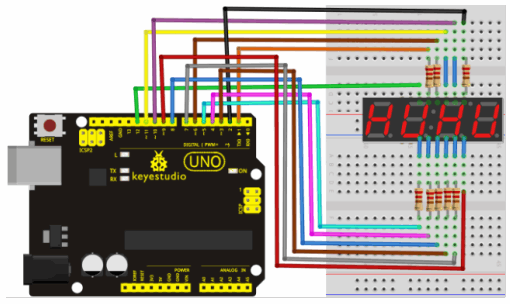
Sample Code:
// display 1234 // select pin for cathode int a = 1; int b = 2; int c = 3; int d = 4; int e = 5; int f = 6; int g = 7; int dp = 8; // select pin for anode int d4 = 9; int d3 = 10; int d2 = 11; int d1 = 12; // set variable long n = 1230; int x = 100; int del = 55; // fine adjustment for clock void setup() { pinMode(d1, OUTPUT); pinMode(d2, OUTPUT); pinMode(d3, OUTPUT); pinMode(d4, OUTPUT); pinMode(a, OUTPUT); pinMode(b, OUTPUT); pinMode(c, OUTPUT); pinMode(d, OUTPUT); pinMode(e, OUTPUT); pinMode(f, OUTPUT); pinMode(g, OUTPUT); pinMode(dp, OUTPUT); }/////////////////////////////////////////////////////////////void loop(){ Display(1, 1); Display(2, 2); Display(3, 3); Display(4, 4);}///////////////////////////////////////////////////////////////void WeiXuan(unsigned char n)//{ switch(n) { case 1: digitalWrite(d1,LOW); digitalWrite(d2, HIGH); digitalWrite(d3, HIGH); digitalWrite(d4, HIGH); break; case 2: digitalWrite(d1, HIGH); digitalWrite(d2, LOW); digitalWrite(d3, HIGH); digitalWrite(d4, HIGH); break; case 3: digitalWrite(d1,HIGH); digitalWrite(d2, HIGH); digitalWrite(d3, LOW); digitalWrite(d4, HIGH); break; case 4: digitalWrite(d1, HIGH); digitalWrite(d2, HIGH); digitalWrite(d3, HIGH); digitalWrite(d4, LOW); break; default : digitalWrite(d1, HIGH); digitalWrite(d2, HIGH); digitalWrite(d3, HIGH); digitalWrite(d4, HIGH); break; }}void Num_0(){ digitalWrite(a, HIGH); digitalWrite(b, HIGH); digitalWrite(c, HIGH); digitalWrite(d, HIGH); digitalWrite(e, HIGH); digitalWrite(f, HIGH); digitalWrite(g, LOW); digitalWrite(dp,LOW);}void Num_1(){ digitalWrite(a, LOW); digitalWrite(b, HIGH); digitalWrite(c, HIGH); digitalWrite(d, LOW); digitalWrite(e, LOW); digitalWrite(f, LOW); digitalWrite(g, LOW); digitalWrite(dp,LOW);}void Num_2(){ digitalWrite(a, HIGH); digitalWrite(b, HIGH); digitalWrite(c, LOW); digitalWrite(d, HIGH); digitalWrite(e, HIGH); digitalWrite(f, LOW); digitalWrite(g, HIGH); digitalWrite(dp,LOW);}void Num_3(){ digitalWrite(a, HIGH); digitalWrite(b, HIGH); digitalWrite(c, HIGH); digitalWrite(d, HIGH); digitalWrite(e, LOW); digitalWrite(f, LOW); digitalWrite(g, HIGH); digitalWrite(dp,LOW);}void Num_4(){ digitalWrite(a, LOW); digitalWrite(b, HIGH); digitalWrite(c, HIGH); digitalWrite(d, LOW); digitalWrite(e, LOW); digitalWrite(f, HIGH); digitalWrite(g, HIGH); digitalWrite(dp,LOW);}void Num_5(){ digitalWrite(a, HIGH); digitalWrite(b, LOW); digitalWrite(c, HIGH); digitalWrite(d, HIGH); digitalWrite(e, LOW); digitalWrite(f, HIGH); digitalWrite(g, HIGH); digitalWrite(dp,LOW);}void Num_6(){ digitalWrite(a, HIGH); digitalWrite(b, LOW); digitalWrite(c, HIGH); digitalWrite(d, HIGH); digitalWrite(e, HIGH); digitalWrite(f, HIGH); digitalWrite(g, HIGH); digitalWrite(dp,LOW);}void Num_7(){ digitalWrite(a, HIGH); digitalWrite(b, HIGH); digitalWrite(c, HIGH); digitalWrite(d, LOW); digitalWrite(e, LOW); digitalWrite(f, LOW); digitalWrite(g, LOW); digitalWrite(dp,LOW);}void Num_8(){ digitalWrite(a, HIGH); digitalWrite(b, HIGH); digitalWrite(c, HIGH); digitalWrite(d, HIGH); digitalWrite(e, HIGH); digitalWrite(f, HIGH); digitalWrite(g, HIGH); digitalWrite(dp,LOW);}void Num_9(){ digitalWrite(a, HIGH); digitalWrite(b, HIGH); digitalWrite(c, HIGH); digitalWrite(d, HIGH); digitalWrite(e, LOW); digitalWrite(f, HIGH); digitalWrite(g, HIGH); digitalWrite(dp,LOW);}void Clear() // clear the screen{ digitalWrite(a, LOW); digitalWrite(b, LOW); digitalWrite(c, LOW); digitalWrite(d, LOW); digitalWrite(e, LOW); digitalWrite(f, LOW); digitalWrite(g, LOW); digitalWrite(dp,LOW);}void pickNumber(unsigned char n)// select number{ switch(n) { case 0:Num_0(); break; case 1:Num_1(); break; case 2:Num_2(); break; case 3:Num_3(); break; case 4:Num_4(); break; case 5:Num_5(); break; case 6:Num_6(); break; case 7:Num_7(); break; case 8:Num_8(); break; case 9:Num_9(); break; default:Clear(); break; }}void Display(unsigned char x, unsigned char Number)// take x as coordinate and display number{ WeiXuan(x); pickNumber(Number); delay(1); Clear() ; // clear the screen}
Result: Project 19: 8*8 LED Matrix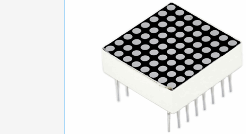
Introduction:
With low-voltage scanning, LED dot-matrix displays have advantages such as power saving, long service life, low cost, high brightness, wide angle of view, long visual range, waterproof, and numerous specifications. LED dot-matrix displays can meet the needs of different applications and thus have a broad development prospect. This time, we will conduct an LED dot-matrix experiment to experience its charm firsthand. Mit der Niederspannungsabtastung haben LED-Punktmatrixanzeigen Vorteile wie Energieeinsparung, lange Lebensdauer, niedrige Kosten, hohe Helligkeit, großer Sichtwinkel, lange Sichtweite, Wasserdichtigkeit und zahlreiche Spezifikationen. LED-Dot-Matrix-Displays können die Anforderungen unterschiedlicher Anwendungen erfüllen und haben somit eine breite Entwicklungsperspektive. Dieses Mal werden wir ein LED-Dot-Matrix-Experiment durchführen, um seinen Charme aus erster Hand zu erfahren.
Hardware required:
8x8 dot-matrix
8x Resistor 220R
BreadBoard 2x 74HC595 USB cable Jumper wires
Connection :
The external view of a dot-matrix is shown as follows:
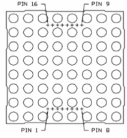
The display principle of the 8*8 dot-matrix:
Das Anzeigeprinzip der 8 * 8 Dot-Matrix:
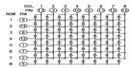
The principle of 74HC595 has been previously illustrated. One chip is used to control the rows of the dot-matrix while the other chip is used to control the columns. Connect circuit as shown in the following diagram: Connection for UNO R3: 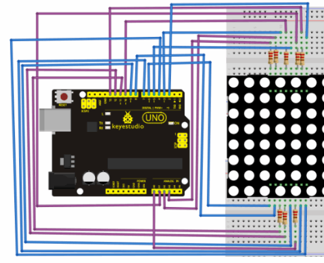
Sample Code for Displaying “0”:
// set an array to store character of “0”unsigned char Text[]={0x00,0x1c,0x22,0x22,0x22,0x22,0x22,0x1c};void Draw_point(unsigned char x,unsigned char y)// point drawing function{ clear_(); digitalWrite(x+2, HIGH); digitalWrite(y+10, LOW); delay(1);}void show_num(void)// display function, call point drawing function{ unsigned char i,j,data; for(i=0;i<8;i++) { data=Text[i]; for(j=0;j<8;j++) { if(data & 0x01)Draw_point(j,i); data>>=1; } }}void setup(){ int i = 0 ; for(i=2;i<18;i++) { pinMode(i, OUTPUT); } clear_(); }void loop(){ show_num(); } void clear_(void)// clear screen{for(int i=2;i<10;i++) digitalWrite(i, LOW); for(int i=0;i<8;i++) digitalWrite(i+10, HIGH);}}
Result: Project 20: 1602 LCDIntroduction:
In this experiment, we use an Arduino to drive the 1602 LCD. 1602LCD main parameters: Display Capacity: 16x2 characters. Chip Operating Voltage: 4,5..5,5V. Working Current: 2,0mA (5V). Optimum working voltage of the module is 5V. Character Size: 2,95x 4.35mm. Pin description of 1602 LCD:
Interface Description:
1. zwei Stromquellen, eine für Modul-Power, eine andere für Hintergrundbeleuchtung, im Allgemeinen 5V verwenden. In diesem Projekt verwenden wir 3.3V für Hintergrundbeleuchtung.
4 Basic Operations of 1602LCD:
Hardware Required: Controller Board ARDUINO UNO R3 1602 LCD Potentiometer BreadBoard
USB Cable
Jumper Wires Connection & Sample Program: 1602 can directly communicate with Arduino. According to the product manual, it has two connection methods, namely 8-bit connection and 4-bit connection.
8-bit connection method:
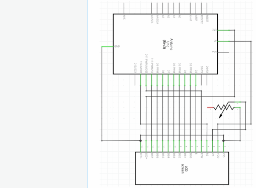
Connection for UNO R3: 
Sample Code A :
int DI = 12;int RW = 11;int DB[] = {3, 4, 5, 6, 7, 8, 9, 10};// use array to select pin for busint Enable = 2;void LcdCommandWrite(int value) {// define all pinsint i = 0;for (i=DB[0]; i <= DI; i++) // assign value for bus{ digitalWrite(i,value & 01);// for 1602 LCD, it uses D7-D0( not D0-D7) for signal identification; here, it’s used for signal inversion. value >>= 1;}digitalWrite(Enable,LOW);delayMicroseconds(1);digitalWrite(Enable,HIGH);delayMicroseconds(1); // wait for 1msdigitalWrite(Enable,LOW);delayMicroseconds(1); // wait for 1ms}void LcdDataWrite(int value) {// initialize all pinsint i = 0;digitalWrite(DI, HIGH);digitalWrite(RW, LOW);for (i=DB[0]; i <= DB[7]; i++) { digitalWrite(i,value & 01); value >>= 1;}digitalWrite(Enable,LOW);delayMicroseconds(1);digitalWrite(Enable,HIGH);delayMicroseconds(1);digitalWrite(Enable,LOW);delayMicroseconds(1); // wait for 1ms}void setup (void) {int i = 0;for (i=Enable; i <= DI; i++) { pinMode(i,OUTPUT);}delay(100);// initialize LCD after a brief pause// for LCD controlLcdCommandWrite(0x38); // select as 8-bit interface, 2-line display, 5x7 character size delay(64); LcdCommandWrite(0x38); // select as 8-bit interface, 2-line display, 5x7 character size delay(50); LcdCommandWrite(0x38); // select as 8-bit interface, 2-line display, 5x7 character size delay(20); LcdCommandWrite(0x06); // set input mode // auto-increment, no display of shiftingdelay(20); LcdCommandWrite(0x0E); // display setup // turn on the monitor, cursor on, no flickeringdelay(20); LcdCommandWrite(0x01); // clear the scree, cursor position returns to 0delay(100); LcdCommandWrite(0x80); // display setup // turn on the monitor, cursor on, no flickeringdelay(20); }void loop (void) { LcdCommandWrite(0x01); // clear the scree, cursor position returns to 0 delay(10); LcdCommandWrite(0x80+3); delay(10); // write in welcome message LcdDataWrite('W'); LcdDataWrite('e'); LcdDataWrite('l'); LcdDataWrite('c'); LcdDataWrite('o'); LcdDataWrite('m'); LcdDataWrite('e'); LcdDataWrite(' '); LcdDataWrite('t'); LcdDataWrite('o'); delay(10); LcdCommandWrite(0xc0+1); // set cursor position at second line, second position delay(10); LcdDataWrite('g'); LcdDataWrite('e'); LcdDataWrite('e'); LcdDataWrite('k'); LcdDataWrite('-'); LcdDataWrite('w'); LcdDataWrite('o'); LcdDataWrite('r'); LcdDataWrite('k'); LcdDataWrite('s'); LcdDataWrite('h'); LcdDataWrite('o'); LcdDataWrite('p'); delay(5000); LcdCommandWrite(0x01); // clear the screen, cursor returns to 0 delay(10); LcdDataWrite('I'); LcdDataWrite(' '); LcdDataWrite('a'); LcdDataWrite('m'); LcdDataWrite(' '); LcdDataWrite('h'); LcdDataWrite('o'); LcdDataWrite('n'); LcdDataWrite('g'); LcdDataWrite('y'); LcdDataWrite('i'); delay(3000); LcdCommandWrite(0x02); // set mode as new characters replay old ones, where there is no new ones remain the same delay(10); LcdCommandWrite(0x80+5); // set cursor position at first line, sixth position delay(10); LcdDataWrite('t'); LcdDataWrite('h'); LcdDataWrite('e'); LcdDataWrite(' '); LcdDataWrite('a'); LcdDataWrite('d'); LcdDataWrite('m'); LcdDataWrite('i'); LcdDataWrite('n'); delay(5000);}}
4-bit connection method: When using this module, 8-bit connection uses all the digital pins of the Arduino, leaving no pin for sensors. What then? We can use 4-bit connection.
Connection circuit: 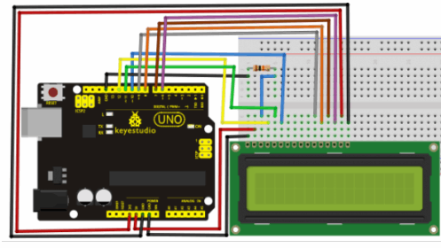
Sample Code B : int LCD1602_RS=12; int LCD1602_RW=11; int LCD1602_EN=10; int DB[] = { 6, 7, 8, 9};char str1[]="Welcome to";char str2[]="geek-workshop";char str3[]="this is the";char str4[]="4-bit interface";void LCD_Command_Write(int command){int i,temp;digitalWrite( LCD1602_RS,LOW);digitalWrite( LCD1602_RW,LOW);digitalWrite( LCD1602_EN,LOW);temp=command & 0xf0;for (i=DB[0]; i <= 9; i++){ digitalWrite(i,temp & 0x80); temp <<= 1;}digitalWrite( LCD1602_EN,HIGH);delayMicroseconds(1);digitalWrite( LCD1602_EN,LOW);temp=(command & 0x0f)<<4;for (i=DB[0]; i <= 10; i++){ digitalWrite(i,temp & 0x80); temp <<= 1;}digitalWrite( LCD1602_EN,HIGH);delayMicroseconds(1); digitalWrite( LCD1602_EN,LOW);}void LCD_Data_Write(int dat){int i=0,temp;digitalWrite( LCD1602_RS,HIGH);digitalWrite( LCD1602_RW,LOW);digitalWrite( LCD1602_EN,LOW);temp=dat & 0xf0;for (i=DB[0]; i <= 9; i++){ digitalWrite(i,temp & 0x80); temp <<= 1;}digitalWrite( LCD1602_EN,HIGH);delayMicroseconds(1);digitalWrite( LCD1602_EN,LOW);temp=(dat & 0x0f)<<4;for (i=DB[0]; i <= 10; i++){ digitalWrite(i,temp & 0x80); temp <<= 1;}digitalWrite( LCD1602_EN,HIGH);delayMicroseconds(1); digitalWrite( LCD1602_EN,LOW);}void LCD_SET_XY( int x, int y ){ int address; if (y ==0) address = 0x80 + x; else address = 0xC0 + x; LCD_Command_Write(address); }void LCD_Write_Char( int x,int y,int dat){ LCD_SET_XY( x, y ); LCD_Data_Write(dat);}void LCD_Write_String(int X,int Y,char *s){ LCD_SET_XY( X, Y ); // address setup while (*s) // write character string { LCD_Data_Write(*s); s ++; }}void setup (void) { int i = 0; for (i=6; i <= 12; i++) { pinMode(i,OUTPUT); } delay(100); LCD_Command_Write(0x28);// 4 wires, 2 lines 5x7 delay(50); LCD_Command_Write(0x06); delay(50); LCD_Command_Write(0x0c); delay(50); LCD_Command_Write(0x80); delay(50); LCD_Command_Write(0x01); delay(50); }void loop (void){ LCD_Command_Write(0x01); delay(50); LCD_Write_String(3,0,str1);// line 1, start at the fourth address delay(50); LCD_Write_String(1,1,str2);// line 2, start at the second address delay(5000); LCD_Command_Write(0x01); delay(50); LCD_Write_String(0,0,str3); delay(50); LCD_Write_String(0,1,str4); delay(5000);}
Project 21: 9g Servo ControlIntroduction: Servomotor is a position control rotary actuator. It mainly consists of housing, circuit board, core-less motor, gear and position sensor. The receiver or MCU outputs a signal to the servomotor. The motor has a built-in reference circuit that gives out reference signal, cycle of 20ms and width of 1.5ms. The motor compares the acquired DC bias voltage to the voltage of the potentiometer and outputs a voltage difference. The IC on the circuit board will decide the rotate direction accordingly and drive the core-less motor. The gear then pass the force to the shaft. The sensor will determine if it has reached the commanded position according to the feedback signal. Servomotors are used in control systems that requires to have and maintain different angles. When the motor speed is definite, the gear will cause the potentiometer to rotate. When the voltage difference reduces to zero, the motor stops. Normally, the rotation angle range is among 0-180 degrees. Der Servomotor ist ein Stellungsregler. Es besteht hauptsächlich aus Gehäuse, Leiterplatte, kernlosem Motor, Getriebe und Positionssensor. Der Empfänger oder die MCU gibt ein Signal an den Servomotor aus. Der Motor hat eine eingebaute Referenzschaltung, die ein Referenzsignal ausgibt, einen Zyklus von 20 ms und eine Breite von 1,5 ms. Der Motor vergleicht die erfasste DC-Vorspannung mit der Spannung des Potentiometers und gibt eine Spannungsdifferenz aus. Der IC auf der Leiterplatte wird die Drehrichtung entsprechend bestimmen und den kernlosen Motor antreiben. Das Zahnrad gibt dann die Kraft an die Welle weiter. Der Sensor wird feststellen, ob er gemäß dem Rückkopplungssignal die befohlene Position erreicht hat. Servomotoren werden in Steuerungssystemen verwendet, die unterschiedliche Winkel aufweisen und beibehalten müssen. Wenn die Motordrehzahl festgelegt ist, dreht das Zahnrad das Potentiometer. Wenn die Spannungsdifferenz auf Null sinkt, stoppt der Motor. Normalerweise liegt der Drehwinkelbereich zwischen 0-180 Grad. 
Servomotor comes with many specifications. But all of them have three connection wires, distinguished by brown, red, orange colors(different brand may have different color). Brown one is for GND, red one for power positive, orange one for signal line. 
The rotate angle of the servo motor is controlled by regulating the duty cycle of the PWM(Pulse-Width Modulation) signal. The standard cycle of the PWM signal is 20ms(50Hz). Theoretically, the width is distributed between 1ms-2ms, but in fact, it's between 0.5ms-2.5ms. The width corresponds the rotate angle from 0° to 180°. But note that for different brand motor, the same signal may have different rotate angle. Der Rotationswinkel des Servomotors wird durch Regulieren des Arbeitszyklus des PWM-Signals (Pulsweitenmodulation) gesteuert. Der Standardzyklus des PWM-Signals beträgt 20 ms (50 Hz). Theoretisch ist die Breite zwischen 1 ms und 2 ms verteilt, tatsächlich liegt sie zwischen 0,5 ms und 2,5 ms. Die Breite entspricht dem Drehwinkel von 0 ° bis 180 °. Beachten Sie jedoch, dass für verschiedene Markenmotoren dasselbe Signal einen anderen Drehwinkel haben kann. 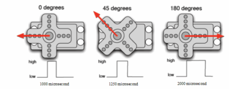
After some basic knowledge, let's learn how to control a servomotor. For this experiment, you only need a servomotor and several jumper wires.
RB-412 servomotor BreadBoard jumper wire*several Connection & Sample Program: There are two ways to control a servomotor with Arduino. One is to use a common digital sensor port of Arduino to produce square wave with different duty cycle to simulate PWM signal and use that signal to control the positioning of the motor. Another way is to directly use the Servo function of the Arduino to control the motor. In this way, the program will be easier but it can only control two-contact motor because for the servo function, only digital pin 9 ang 10 can be used. The Arduino drive capacity is limited. So if you need to control more than one motor, you will need external power. Method 1: Connection for UNO R3: 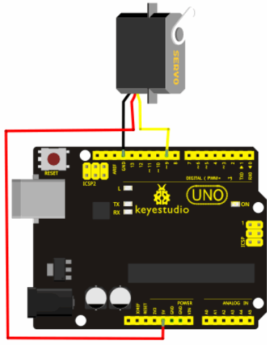
Connect the motor to digital pin 9.Compile a program to control the motor to rotate to the commanded angle input by the user and display the angle on the screen.
Sample Code A :
int servopin=9;// select digital pin 9 for servomotor signal lineint myangle;// initialize angle variableint pulsewidth;// initialize width variableint val;void servopulse(int servopin,int myangle)// define a servo pulse function{pulsewidth=(myangle*11)+500;// convert angle to 500-2480 pulse widthdigitalWrite(servopin,HIGH);// set the level of servo pin as “high”delayMicroseconds(pulsewidth);// delay microsecond of pulse widthdigitalWrite(servopin,LOW);// set the level of servo pin as “low”delay(20-pulsewidth/1000);}void setup(){pinMode(servopin,OUTPUT);// set servo pin as “output”Serial.begin(9600);// connect to serial port, set baud rate at “9600”Serial.println("servo=o_seral_simple ready" ) ;}void loop()// convert number 0 to 9 to corresponding 0-180 degree angle, LED blinks corresponding number of time{val=Serial.read();// read serial port valueif(val>='0'&&val<='9'){val=val-'0';// convert characteristic quantity to numerical variableval=val*(180/9);// convert number to angleSerial.print("moving servo to ");Serial.print(val,DEC);Serial.println();for(int i=0;i<=50;i++) // giving the servo time to rotate to commanded position{servopulse(servopin,val);// use the pulse function}}}}
Method 2::
Let's first take a look at the Arduino built-in servo function and some of its common statements.
Werfen wir zunächst einen Blick auf die integrierte Arduino-Servofunktion und einige ihrer allgemeinen Aussagen.
#include <Servo.h>// define a header file. Special attention here, you can call the servo function directly from Arduino's software menu bar Sketch>Importlibrary>Servo, or input #include <Servo.h>. Make sure there is a space between #include and <Servo.h>. Otherwise, it will cause compile error.Servo myservo;// define servo variable namevoid setup(){myservo.attach(9);// select servo pin(9 or 10)}void loop(){myservo.write(90);// set rotate angle of the motor}}
Above are the two methods to control the servo. You can choose either one according to your liking or actual need.
Resources Video http://www.keyestudio.com/wp/ks0069-72-73/
303_d_arduino-x_keyestudio Basic Starter Kit for Arduino UNO - Tutorial engl. (109 Seiten)_1a.pdf
Buy from
Official Website With UNO
http://www.keyestudio.com/keyestudio-basic-starter-kit-for-arduino-starter-with-uno-r3.html
No Board
http://www.keyestudio.com/keyestudio-basic-starter-kit-for-arduino-starter-no-board.html
With 2560 R3
********************************************************I*
==keyestudio Basic Starter Kit for UNO and Mega==
<br>[[File:691.png|500px|frameless|thumb]]<br> ==1. Kit Introduction== This is the basic Starter Kit, developed specially for those beginners who are interested in Arduino. You will have a set of Arduino's most common and useful electronic components. What's more. We will offer you a detailed tutorials including project introduction and their source codes.You may learn about Arduino through using these basic projects. This kit will help you control the physical world with sensors. <br>[[File:692.png|500px|frameless|thumb]]<br> ==2.Kit Contents == {| width="80%" cellspacing="0" border="1" |- ! align="center" scope="col" | Kit A for unoR3 ! align="center" scope="col" | Kit B for 2560 R3 ! align="center" scope="col" | Kit C Without board |- | align="center" | UNO R3 | align="center" | Mega 2560 | align="center" | No controller board |- | align="center" | 5x LED - Blue | align="center" | 5x LED - Blue | align="center" | 5x LED - Blue |- | align="center" | 5x LED - Red | align="center" | 5x LED - Red | align="center" | 5x LED - Red |- | align="center" | 5x LED - Yellow | align="center" | 5x LED - Yellow | align="center" | 5x LED - Yellow |- | align="center" | 1x LED - RGB | align="center" | 1x LED - RGB | align="center" | 1x LED - RGB |- | align="center" | 5x 10K Ω resistor | align="center" | 5x 10K Ω resistor | align="center" | 5x 10K Ω resistor |- | align="center" | 5x 1K Ω resistor | align="center" | 5x 1K Ω resistor | align="center" | 5x 1K Ω resistor |- | align="center" | 8x 220 Ω resistor | align="center" | 8x 220 Ω resistor | align="center" | 8x 220 Ω resistor |- | align="center" | 1x 10K Ω Pot | align="center" | 1x 10K Ω Pot | align="center" | 1x 10K Ω Pot |- | align="center" | 1x 7-seg LED 1x module | align="center" | 1x 7-seg LED 1x module | align="center" | 1x 7-seg LED 1x module |- | align="center" | 1x 7-seg LED 4x module | align="center" | 1x 7-seg LED 4x module | align="center" | 1x 7-seg LED 4x module |- | align="center" | 1x 8x8 LED Matrix | align="center" | 1x 8x8 dot LED array | align="center" | 1x 8x8 dot LED array |- | align="center" | 1x Buzzer (active) | align="center" | 1x Buzzer (active) | align="center" | 1x Buzzer (active) |- | align="center" | 1x Buzzer (passive) | align="center" | 1x Buzzer (passive) | align="center" | 1x Buzzer (passive) |- | align="center" | 1x Flame sensor | align="center" | 1x Flame sensor | align="center" | 1x Flame sensor |- | align="center" | 1x IR receiver | align="center" | 1x IR receiver | align="center" | 1x IR receiver |- | align="center" | 1x IR remote control | align="center" | 1x IR remote control | align="center" | 1x IR remote control |- | align="center" | 1x LM35 Temp Sensor | align="center" | 1x LM35 Temp Sensor | align="center" | 1x LM35 Temp Sensor |- | align="center" | 2x Ball tilt sensor | align="center" | 2x Ball tilt sensor | align="center" | 2x Ball tilt sensor |- | align="center" | 3x Photo Resistor | align="center" | 3x Photo Resistor | align="center" | 3x Photo Resistor |- | align="center" | 4x Small button switch | align="center" | 4x Small button switch | align="center" | 4x Small button switch |- | align="center" | 1x IC 74HC595N 16-pin DIP | align="center" | 1x IC 74HC595N 16-pin DIP | align="center" | 1x IC 74HC595N 16-pin DIP |- | align="center" | 1x LCD1602 | align="center" | 1x LCD1602 | align="center" | 1x LCD1602 |- | align="center" | 1x 9g servo | align="center" | 1x 9g servo | align="center" | 1x 9g servo |- | align="center" | 830-pin Breadboard | align="center" | 830-pin Breadboard | align="center" | 830-pin Breadboard |- | align="center" | Dupont connector wires | align="center" | Dupont connector wires | align="center" | Dupont connector wires |- | align="center" | 1x 6-cell AA Battery pack | align="center" | 1x 6-cell AA Battery pack | align="center" | 1x 6-cell AA Battery pack |- | align="center" | 1x USB cable | align="center" | 1x USB cable | align="center" | 1x USB cable |} ==3. Project List== 1.Hello World <br> 2.LED Blinking<br> 3.PWM<br> 4.Traffic Light<br> 5.LED Chase Effect<br> 6.Button-controlled LED<br> 7.Active Buzzer<br> 8.Passive Buzzer<br> 9.RGB LED<br> 10.Photo Resistor<br> 11.Flame Sensor<br> 12.LM35 Temperature Sensor<br> 13.Tilt Switch<br> 14.IR Remote Control<br> 15.Analog Value Reading<br> 16.74HC595<br> 17.1-digit LED Segment Display<br> 18.4-digit LED Segment Display<br> 19.8*8 LED Matrix<br> 20.1602 LCD<br> 21.9g Servo Control<br> ==4. Project Details == === '''Project 1: Hello World'''=== '''Introduction:''' As for starters, we will begin with something simple. In this project, you only need an Arduino and a USB cable to start the "Hello World!" experiment. This is a communication test of your Arduino and PC, also a primer project for you to have your first try of the Arduino world!<br> '''Hardware Required:'''<br> 1. Arduino board x1<br> 2. USB cable x1<br> '''Sample Code:'''<br> After installing driver for Arduino, let's open Arduino software and compile code that enables Arduino to print "Hello World!" under your instruction. Of course, you can compile code for Arduino to continuously echo "Hello World!" without instruction. A simple If () statement will do the instruction trick. With the onboard LED connected to pin 13, we can instruct the LED to blink first when Arduino gets an instruction and then print "Hello World!”. <pre> int val;//define variable val int ledpin=13;// define digital interface 13 void setup() { Serial.begin(9600);// set the baud rate at 9600 to match the software set up. When connected to a specific device, (e.g. bluetooth), the baud rate needs to be the same with it. pinMode(ledpin,OUTPUT);// initialize digital pin 13 as output. When using I/O ports on an Arduino, this kind of set up is always needed. } void loop() { val=Serial.read();// read the instruction or character from PC to Arduino, and assign them to Val. if(val=='R')// determine if the instruction or character received is “R”. { // if it’s “R”, digitalWrite(ledpin,HIGH);// set the LED on digital pin 13 on. delay(500); digitalWrite(ledpin,LOW);// set the LED on digital pin 13 off. delay(500); Serial.println("Hello World!");// display“Hello World!”string. }</pre> '''Result:'''<br> Screenshot<br> <br>[[File:693.png|500px|frameless|thumb]]<br> Click serial port monitor<br> Input R<br> LED 13 will blink once;<br> PC will receive information from Arduino: Hello World<br> <br>[[File:694.png|500px|frameless|thumb]]<br> After you choose the right port, the experiment should be easy for you! === '''Project 2: LED Blinking'''=== '''Introduction:''' Blinking LED experiment is quite simple. In the "Hello World!" program, we have come across LED. This time, we are going to connect an LED to one of the digital pins rather than using LED13, which is soldered to the board. Except an Arduino and an USB cable, we will need extra parts as below:<br> '''Hardware Required:'''<br> 1. Red M5 LED*1 <br> 2. 220Ω resistor*1<br> 3. Breadboard*1<br> 4. Breadboard jumper wires* several <br> We follow below diagram from the experimental schematic link. Here we use digital pin 10. We connect LED to a 220 ohm resistor to avoid high current damaging the LED. '''Connection for UNO R3:''' <br>[[File:695.png|500px|frameless|thumb]]<br> '''Connection for 2560 R3:''' <br>[[File:696.png|500px|frameless|thumb]]<br> '''Sample Code:'''<br> <pre> int ledPin = 10; // define digital pin 10. void setup() { pinMode(ledPin, OUTPUT);// define pin with LED connected as output. } void loop() { digitalWrite(ledPin, HIGH); // set the LED on. delay(1000); // wait for a second. digitalWrite(ledPin, LOW); // set the LED off. delay(1000); // wait for a second }</pre> '''Result:'''<br> After downloading this program, in the experiment, you will see the LED connected to pin 10 turning on and off, with an interval approximately one second. The blinking LED experiment is now completed. Thank you! === '''Project 3: PWM'''=== '''Introduction:''' PWM, short for Pulse Width Modulation, is a technique used to encode analog signal level into digital ones. A computer cannot output analog voltage but only digital voltage values such as 0V or 5V. So we use a high resolution counter to encode a specific analog signal level by modulating the duty cycle of PMW. The PWM signal is also digitalized because in any given moment, fully on DC power supply is either 5V (ON), or 0V (OFF). The voltage or current is fed to the analog load (the device that uses the power) by repeated pulse sequence being ON or OFF. Being on, the current is fed to the load; being off, it's not. With adequate bandwidth, any analog value can be encoded using PWM. The output voltage value is calculated via the on and off time. Output voltage = (turn on time/pulse time) * maximum voltage value<br> <br>[[File:697.png|500px|frameless|thumb]]<br> PWM has many applications: lamp brightness regulating, motor speed regulating, sound making, etc. The following are the three basic parameters of PMW: <br>[[File:698.png|500px|frameless|thumb]]<br> 1. The amplitude of pulse width (minimum / maximum)<br> 2. The pulse period (The reciprocal of pulse frequency in 1 second)<br> 3. The voltage level(such as:0V-5V)<br> There are 6 PMW interfaces on Arduino, namely digital pin 3, 5, 6, 9, 10, and 11. In previous experiments, we have done "button-controlled LED", using digital signal to control digital pin, also one about potentiometer. This time, we will use a potentiometer to control the brightness of the LED.<br> '''Hardware Required:'''<br> 1. Potentiometer*1 <br> 2. Red M5 LED*1<br> 3. 220Ω resistor<br> 4. Breadboard*1 <br> 5. Breadboard jumper wires*several<br> The input of potentiometer is analog, so we connect it to analog port, and LED to PWM port. Different PWM signal can regulate the brightness of the LED.<br> '''Connection for UNO R3:''' <br>[[File:699.png|500px|frameless|thumb]]<br> '''Connection for 2560 R3:''' <br>[[File:6910.png|500px|frameless|thumb]]<br> '''Sample Code:'''<br> In the program compiling process, we will use the analogWrite (PWM interface, analog value) function. In this experiment, we will read the analog value of the potentiometer and assign the value to PWM port, so there will be corresponding change to the brightness of the LED. One final part will be displaying the analog value on the screen. You can consider this as the "analog value reading" project adding the PWM analog value assigning part. Below is a sample program for your reference. <pre> int potpin=0;// initialize analog pin 0 int ledpin=11;//initialize digital pin 11(PWM output) int val=0;// Temporarily store variables' value from the sensor void setup() { pinMode(ledpin,OUTPUT);// define digital pin 11 as “output” Serial.begin(9600);// set baud rate at 9600 // attention: for analog ports, they are automatically set up as “input” } void loop() { val=analogRead(potpin);// read the analog value from the sensor and assign it to val Serial.println(val);// display value of val analogWrite(ledpin,val/4);// turn on LED and set up brightness(maximum output of PWM is 255) delay(10);// wait for 0.01 second }</pre> <br>[[File:6911.png|500px|frameless|thumb]]<br> '''Result:'''<br> After downloading the program, when we rotate the potentiometer knob, we can see changes of the displaying value, also obvious change of the LED brightness on the breadboard. === '''Project 4: Traffic Light'''=== '''Introduction:''' In the previous program, we have done the LED blinking experiment with one LED. Now, it’s time to up the stakes and do a bit more complicated experiment-traffic lights. Actually, these two experiments are similar. While in this traffic lights experiment, we use 3 LEDs with different color other than 1 LED. <br> '''Hardware Required:'''<br> 1. Arduino board *1<br> 2. USB cable *1<br> 3. Red M5 LED*1 <br> 4. Yellow M5 LED*1<br> 5. Green M5 LED*1<br> 6. 220Ω resistor *3 <br> 7. Breadboard*1 <br> 8. Breadboard jumper wires* several<br> '''Connection for UNO R3:''' <br>[[File:6912.png|500px|frameless|thumb]]<br> '''Connection for 2560 R3:''' <br>[[File:6913.png|500px|frameless|thumb]]<br> '''Sample Code:'''<br> Since it is a simulation of traffic lights, the blinking time of each LED should be the same with those in traffic lights system. In this program, we use Arduino delay () function to control delay time, which is much simpler than C language. <pre> int redled =10; // initialize digital pin 8. int yellowled =7; // initialize digital pin 7. int greenled =4; // initialize digital pin 4. void setup() { pinMode(redled, OUTPUT);// set the pin with red LED as “output” pinMode(yellowled, OUTPUT); // set the pin with yellow LED as “output” pinMode(greenled, OUTPUT); // set the pin with green LED as “output” } void loop() { digitalWrite(greenled, HIGH);//// turn on green LED delay(5000);// wait 5 seconds digitalWrite(greenled, LOW); // turn off green LED for(int i=0;i<3;i++)// blinks for 3 times { delay(500);// wait 0.5 second digitalWrite(yellowled, HIGH);// turn on yellow LED delay(500);// wait 0.5 second digitalWrite(yellowled, LOW);// turn off yellow LED } delay(500);// wait 0.5 second digitalWrite(redled, HIGH);// turn on red LED delay(5000);// wait 5 second digitalWrite(redled, LOW);// turn off red LED }</pre> '''Result:'''<br> When the uploading process is completed, we can see traffic lights of our own design. Note: this circuit design is very similar with the one in LED chase effect. The green light will be on for 5 seconds, and then off., followed by the yellow light blinking for 3 times, and then the red light on for 5 seconds, forming a cycle. Cycle then repeats. Experiment is now completed, thank you. === '''Project 5: LED Chasing Effect'''=== '''Introduction:''' We often see billboards composed of colorful LEDs. They are constantly changing to form various effects. In this experiment, we compile a program to simulate chase effect.<br> '''Hardware Required:'''<br> 1. Led x6<br> 2. 220Ω resistor x6 <br> 3. Colorful breadboard wires<br> '''Connection for UNO R3:''' <br>[[File:6914.png|500px|frameless|thumb]]<br> '''Connection for 2560 R3:''' <br>[[File:6915.png|500px|frameless|thumb]]<br> '''Sample Code:'''<br> <pre> int BASE = 2 ; // the I/O pin for the first LED int NUM = 6; // number of LEDs void setup() { for (int i = BASE; i < BASE + NUM; i ++) { pinMode(i, OUTPUT); // set I/O pins as output } } void loop() { for (int i = BASE; i < BASE + NUM; i ++) { digitalWrite(i, LOW); // set I/O pins as “low”, turn off LEDs one by one. delay(200); // delay } for (int i = BASE; i < BASE + NUM; i ++) { digitalWrite(i, HIGH); // set I/O pins as “high”, turn on LEDs one by one delay(200); // delay }</pre> '''Result:'''<br> You can see the LEDs blink by sequence. === '''Project 6: Button-controlled LED'''=== '''Introduction:''' I/O port means interface for INPUT and OUTPUT. Up until now, we have only used its OUTPUT function. In this experiment, we will try to use the input function, which is to read the output value of device connecting to it. We use 1 button and 1 LED using both input and output to give you a better understanding of the I/O function. Button switches, familiar to most of us, are a switch value (digital value) component. When it's pressed, the circuit is in closed (conducting) state.<br> '''Hardware Required:'''<br> 1. Button switch*1 <br> 2. Red M5 LED*1 <br> 3. 220Ω resistor*1<br> 4. 10KΩ resistor*1 <br> 5. Breadboard*1<br> 6. Breadboard jumper wires*several<br> '''Connection for UNO R3:''' <br>[[File:6916.png|500px|frameless|thumb]]<br> '''Connection for 2560 R3:''' <br>[[File:6917.png|500px|frameless|thumb]]<br> '''Sample Code:'''<br> Now, let's begin the compiling. When the button is pressed, the LED will be on. After the previous study, the coding should be easy for you. In this program, we add a statement of judgment. Here, we use an if () statement.<br> Arduino IDE is based on C language, so statements of C language such as while, switch etc. can certainly be used for Arduino program.<br> When we press the button, pin 7 will output high level. We can program pin 11 to output high level and turn on the LED. When pin 7 outputs low level, pin 11 also outputs low level and the LED remains off. <pre> int ledpin=11;// initialize pin 11 int inpin=7;// initialize pin 7 int val;// define val void setup() { pinMode(ledpin,OUTPUT);// set LED pin as “output” pinMode(inpin,INPUT);// set button pin as “input” } void loop() { val=digitalRead(inpin);// read the level value of pin 7 and assign if to val if(val==LOW)// check if the button is pressed, if yes, turn on the LED { digitalWrite(ledpin,LOW);} else { digitalWrite(ledpin,HIGH);} }</pre> '''Result:'''<br> When the button is pressed, LED is on, otherwise, LED remains off. After the above process, the button controlled LED experiment is completed. The simple principle of this experiment is widely used in a variety of circuit and electric appliances. You can easily come across it in your every day life. One typical example is when you press a certain key of your phone, the backlight will be on. === '''Project 7: Active Buzzer'''=== '''Introduction:''' Active buzzer is widely used on computer, printer, alarm, electronic toy, telephone, timer etc as a sound making element. It has an inner vibration source. Simply connect it with 5V power supply, it can buzz continuously. <br> '''Hardware Required:'''<br> 1. Buzzer*1<br> 2. Key *1 <br> 3. Breadboard*1 <br> 4. Breadboard jumper wires*several<br> '''Connection for UNO R3:''' <br>[[File:6918.png|500px|frameless|thumb]]<br> '''Connection for 2560 R3:''' <br>[[File:6919.png|500px|frameless|thumb]]<br> When connecting the circuit, pay attention to the positive & the negative poles of the buzzer. In the photo, you can see there are red and black lines. When the circuit is finished, you can begin programming. '''Sample Code:'''<br> Program is simple. You control the buzzer by outputting high/low level. <pre> int buzzer=8;// initialize digital IO pin that controls the buzzer void setup() { pinMode(buzzer,OUTPUT);// set pin mode as “output” } void loop() { digitalWrite(buzzer, HIGH); // produce sound }</pre> '''Result:'''<br> After downloading the program, the buzzer experiment is completed. You can see the buzzer is ringing. === '''Project 8: Passive Buzzer'''=== '''Introduction:''' We can use Arduino to make many interactive works of which the most commonly used is acoustic-optic display. All the previous experiment has something to do with LED. However, the circuit in this experiment can produce sound. Normally, the experiment is done with a buzzer or a speaker while buzzer is simpler and easier to use. The buzzer we introduced here is a passive buzzer. It cannot be actuated by itself, but by external pulse frequencies. Different frequencies produce different sounds. We can use Arduino to code the melody of a song, which is actually quite fun and simple. <br> '''Hardware Required:'''<br> 1.Passive buzzer*1<br> 2. Key *1 <br> 3. Breadboard*1 <br> 4. Breadboard jumper wires* several<br> '''Connection for UNO R3:''' <br>[[File:6920.png|500px|frameless|thumb]]<br> '''Connection for 2560 R3:''' <br>[[File:6921.png|500px|frameless|thumb]]<br> '''Sample Code:'''<br> <pre> int buzzer=8;// select digital IO pin for the buzzer void setup() { pinMode(buzzer,OUTPUT);// set digital IO pin pattern, OUTPUT to be output } void loop() { unsigned char i,j;//define variable while(1) { for(i=0;i<80;i++)// output a frequency sound { digitalWrite(buzzer,HIGH);// sound delay(1);//delay1ms digitalWrite(buzzer,LOW);//not sound delay(1);//ms delay } for(i=0;i<100;i++)// output a frequency sound { digitalWrite(buzzer,HIGH);// sound digitalWrite(buzzer,LOW);//not sound delay(2);//2ms delay }</pre> '''Result:'''<br> After downloading the program, the buzzer experiment is completed. === '''Project 9: RGB LED'''=== '''Introduction:''' Tricolor principle to display various colors<br> PWM controlling ports to display full color<br> Can be driven directly by Arduino PWM interfaces <br> '''Hardware Required:'''<br> Arduino controller × 1<br> USB cable × 1<br> Full-color LED module × 1<br> '''Connection for UNO R3:''' <br>[[File:6922.png|500px|frameless|thumb]]<br> '''Connection for 2560 R3:''' <br>[[File:6923.png|500px|frameless|thumb]]<br> '''Sample Code:'''<br> <pre> int redpin = 11; //select the pin for the red LED int bluepin =10; // select the pin for the blue LED int greenpin =9;// select the pin for the green LED int val; void setup() { pinMode(redpin, OUTPUT); pinMode(bluepin, OUTPUT); pinMode(greenpin, OUTPUT); Serial.begin(9600); } void loop() { for(val=255; val>0; val--) { analogWrite(11, val); analogWrite(10, 255-val); analogWrite(9, 128-val); delay(1); } for(val=0; val<255; val++) { analogWrite(11, val); analogWrite(10, 255-val); analogWrite(9, 128-val); delay(1); } Serial.println(val, DEC); }</pre> '''Result:'''<br> Directly copy the above code into arduino IDE, and click upload [[File:690.png|500px|frameless|thumb]], wait a few seconds, you can see a full-color LED === '''Project 10: Photo Resistor'''=== '''Introduction:''' After completing all the previous experiments, we acquired some basic understanding and knowledge about Arduino application. We have learned digital input and output, analog input and PWM. Now, we can begin the learning of sensors applications.<br> Photo resistor (Photovaristor) is a resistor whose resistance varies according to different incident light strength. It's made based on the photoelectric effect of semiconductor. If the incident light is intense, its resistance reduces; if the incident light is weak, the resistance increases. Photovaristor is commonly applied in the measurement of light, light control and photovoltaic conversion (convert the change of light into the change of electricity).<br> Photo resistor is also being widely applied to various light control circuit, such as light control and adjustment, optical switches etc.We will start with a relatively simple experiment regarding photovaristor application. Photovaristor is an element that changes its resistance as light strenth changes. So we will need to read the analog values. We can refer to the PWM experiment, replacing the potentiometer with photovaristor. When there is change in light strength, there will be corresponding change on the LED. '''Hardware Required:'''<br> Photo resistor*1 <br> Red M5 LED*1 <br> 10KΩresistor*1<br> 220Ωresistor*1<br> Bread board*1<br> Bread board jumper wires*several<br> '''Connection for UNO R3:''' <br>[[File:6924.png|500px|frameless|thumb]]<br> '''Connection for 2560 R3:''' <br>[[File:6925.png|500px|frameless|thumb]]<br> '''Sample Code:'''<br> After the connection, let's begin the program compiling. The program is similar to the one of PWM. For change detail, please refer to the sample program below. <pre> int potpin=0;// initialize analog pin 0, connected with photovaristor int ledpin=11;// initialize digital pin 11, output regulating the brightness of LED int val=0;// initialize variable va void setup() { pinMode(ledpin,OUTPUT);// set digital pin 11 as “output” Serial.begin(9600);// set baud rate at “9600” } void loop() { val=analogRead(potpin);// read the analog value of the sensor and assign it to val Serial.println(val);// display the value of val analogWrite(ledpin,val);// turn on the LED and set up brightness(maximum output value 255) delay(10);// wait for 0.01 }</pre> '''Result:'''<br> After downloading the program, you can change the light strength around the photovaristor and see corresponding brightness change of the LED. Photovaristors has various applications in our everyday life. You can make other interesting interactive projects base on this one.
=== '''Project 11: Flame Sensor'''===
'''Introduction:''' Flame sensor (Infrared receiving triode) is specially used on robots to find the fire source. This sensor is of high sensitivity to flame. Below is a photo of it. <br>[[File:6926.png|500px|frameless|thumb]]<br> '''Working Principle:'''<br> Flame sensor is made based on the principle that infrared ray is highly sensitive to flame. It has a specially designed infrared receiving tube to detect fire, and then convert the flame brightness to fluctuating level signal. The signals are then input into the central processor and be dealt with accordingly. '''Sensor Connection:'''<br> The shorter lead of the receiving triode is for negative, the other one for positive. Connect negative to 5V pin, positive to resistor; connect the other end of the resistor to GND, connect one end of a jumper wire to a clip which is electrically connected to sensor positive, the other end to analog pin. As shown below: <br>[[File:6927.png|500px|frameless|thumb]]<br> '''Hardware Required:'''<br> 1. Flame sensor *1 <br> 2. Buzzer *1<br> 3. 10K resistor x1 <br> 4. Breadboard jumper wires: several<br> '''Experiment connection:'''<br> 1)Connecting buzzer:<br> Connect the controller board, prototype board, breadboard and USB cable according to the Arduino tutorial. Connect the buzzer to digital pin 8. 2)Connecting flame sensor:<br> Connect the sensor to analog pin 0. '''Connection for UNO R3:''' <br>[[File:6928.png|500px|frameless|thumb]]<br> '''Connection for 2560 R3:''' <br>[[File:6929.png|500px|frameless|thumb]]<br> '''Experiment principle:'''<br> When it's approaching a fire, the voltage value the analog port reads differs. If you use a multimeter, you can know when there is no fire approaching, the voltage it reads is around 0.3V; when there is fire approaching, the voltage it reads is around 1.0V, tthe nearer the fire, the higher the voltage. So in the beginning of the program, you can initialize voltage value i (no fire value); Then, continuously read the analog voltage value j and obtain difference value k=j-i; compare k with 0.6V (123 in binary) to determine whether or not there is a fire approaching; if yes, the buzzer will buzz. '''Sample Code:'''<br> <pre> int flame=0;// select analog pin 0 for the sensor int Beep=9;// select digital pin 9 for the buzzer int val=0;// initialize variable void setup() { pinMode(Beep,OUTPUT);// set LED pin as “output” pinMode(flame,INPUT);// set buzzer pin as “input” Serial.begin(9600);// set baud rate at “9600” } void loop() { val=analogRead(flame);// read the analog value of the sensor Serial.println(val);// output and display the analog value if(val>=600)// when the analog value is larger than 600, the buzzer will buzz { digitalWrite(Beep,HIGH); }else { digitalWrite(Beep,LOW); } delay(500); }</pre> '''Result:'''<br> This program can simulate an alarm when there is a fire. Everything is normal when there is no fire; when there is, the alarm will be set off immediately.
=== '''Project 12: LM35 Temperature Sensor'''===
'''Introduction:''' LM35 is a common and easy-to-use temperature sensor. It does not require other hardware. You just need an analog port to make it work. The difficulty lies in compiling the code to convert the analog value it reads to celsius temperature. '''Hardware Required:'''<br> 1. LM35*1 <br> 2. Breadboard*1<br> 3. Breadboard jumper wires*several<br> '''Connection for UNO R3:''' <br>[[File:6930.png|500px|frameless|thumb]]<br> '''Connection for 2560 R3:''' <br>[[File:6931.png|500px|frameless|thumb]]<br> '''Sample Code:'''<br> <pre> int potPin = 0; // initialize analog pin 0 for LM35 temperature sensor void setup() { Serial.begin(9600);// set baud rate at”9600” } void loop() { int val;// define variable int dat;// define variable val=analogRead(0);// read the analog value of the sensor and assign it to val dat=(125*val)>>8;// temperature calculation formula Serial.print("Tep:");// output and display characters beginning with Tep Serial.print(dat);// output and display value of dat Serial.println("C");// display “C” characters delay(500);// wait for 0.5 second }</pre> '''Result:'''<br> After downloading the program, you can open the monitoring window to see current temperature. <br>[[File:6932.png|500px|frameless|thumb]]<br> === '''Project 13: Tilt Switch'''=== '''Introduction:''' Tilt switch controlling the ON and OFF of LED '''Hardware Required:'''<br> 1. Ball switch*1<br> 2. Led *1 <br> 3. 220Ω resistor*1<br> 4. 10KΩ resistor*1<br> 4. Breadboard jumper wires:several<br> '''Connection for UNO R3:''' <br>[[File:6933.png|500px|frameless|thumb]]<br> '''Connection for 2560 R3:''' <br>[[File:6934.png|500px|frameless|thumb]]<br> Connect the controller board, shield, breadboard and USB cable according to Arduino tutorial. Connect the LED to digital pin 8, ball switch to analog pin 5. '''Experiment Principle:''' When one end of the switch is below horizontal position, the switch is on. The voltage of the analog port is about 5V (1023 in binary). The LED will be on. When the other end of the switch is below horizontal position, the switch is off. The voltage of the analog port is about 0V (0 in binary). The LED will be off. In the program, we determine whether the switch is on or off according to the voltage value of the analog port, whether it's above 2.5V (512 in binary) or not. '''Sample Code:'''<br> <pre> void setup() { pinMode(8,OUTPUT);// set digital pin 8 as “output” } void loop() { int i;// define variable i while(1) { i=analogRead(5);// read the voltage value of analog pin 5 if(i>512)// if larger that 512(2.5V) { digitalWrite(8,LOW);// turn on LED } else// otherwise { digitalWrite(8,HIGH);// turn off LED }</pre> '''Result:'''<br> Hold the breadboard with your hand. Tilt it to a certain extent, the LED will be on. If there is no tilt, the LED will be off. The principle of this experiment can be applied to relay control. Experiment completed. Thank you! === '''Project 14: IR Remote Control'''=== '''Introduction:''' What is an infrared receiver?<br> The signal from the infrared remote controller is a series of binary pulse code. To avoid interference from other infrared signals during the wireless transmission, the signal is pre-modulate at a specific carrier frequency and then send out by a infrared emission diode. The infrared receiving device needs to filter out other wave and receive signal at that specific frequency and modulate it back to binary pulse code, known as demodulation.<br> '''Working Principal:'''<br> The built-in receiver converts the light signal it received from the sender into feeble electrical signal. The signal will be amplified by the IC amplifier. After automatic gain control, band-pass filtering, demodulation, wave shaping, it returns to the original code. The code is then input to the code identification circuit by the receiver's signal output pin. The pin and the connection of the infrared receiving head.<br> Pin and wiring of infrared receiver:<br> <br>[[File:6935.png|500px|frameless|thumb]]<br> Infrared receiver has 3 pins. When you use it, connect VOUT to analog pin, GND to GND, VCC to +5V. 2. Infrared remote control experiment '''Hardware Required:'''<br> Infrared remote controller x1<br> Infrared receiver x1 <br> LED x6<br> 220Ω resistor x6 <br> Multi-color breadboard wires x several<br> '''Connection:''' First, connect the controller board; then connect the infrared receiver as the above mentioned, connect VOUT to digital pin 11, connect the LEDs with resistors and connect the resisters to pin 2,3,4,5,6,7. '''Connection for UNO R3:''' <br>[[File:6936.png|500px|frameless|thumb]]<br> '''Connection for 2560 R3:''' <br>[[File:6937.png|500px|frameless|thumb]]<br> '''Experimental Principle:''' If you want to decode code of a remote controller, you must first know how it's coded. The coding method we use here is NEC protocol. Below is a brief introduction. ·NEC protocol:<br> Features:<br> (1) 8 bit address and 8 bit command length<br> (2) address and command are transmitted twice for reliability<br> (3) pulse distance modulation<br> (4) carrier frequency of 38 KHZ <br> (5) bit time of 1.125ms or 2.25ms<br> Protocol is as below:<br> * Definition of logical 0 and 1 is as below <br>[[File:6938.png|500px|frameless|thumb]]<br> *Pulse transmitted when button is pressed and immediately released. <br>[[File:6939.png|500px|frameless|thumb]]<br> The picture above shows a typical pulse train of the NEC protocol. With this protocol the LSB is transmitted first. In this case Address $59 and Command $16 is transmitted. A message is started by a 9ms AGC burst, which was used to set the gain of the earlier IR receivers. This AGC burst is then followed by a 4.5ms space, which is then followed by the address and command. Address and Command are transmitted twice. The second time all bits are inverted and can be used for verification of the received message. The total transmission time is constant because every bit is repeated with its inverted length. If you are not interested in this reliability, you can ignore the inverted values, or you can expend the Address and Command to 16 bits each! * Pulse transmitted when button is pressed and released after a period of time <br>[[File:6940.png|500px|frameless|thumb]]<br> A command is transmitted only once, even when the key on the remote control remains pressed. Every 110ms a repeat code is transmitted for as long as the key remains down. This repeat code is simply a 9ms AGC pulse followed by a 2.25ms space and a 560µs burst. *Repeat pulse <br>[[File:6941.png|500px|frameless|thumb]]<br> Note: when the pulse enters the integrated receiver, there will be decoding, signal amplifying and wave shaping process. So you need to make sure the level of the output is just the opposite from that of the signal sending end. That is when there is no infrared signal, the output end is in high level; when there is infrared signal, the output end is in low level. You can see the pulse of the receiving end in the oscilloscope. Try to better understand the program base on what you see. '''Sample Code:'''<br> <pre> #include <IRremote.h> int RECV_PIN = 11; int LED1 = 2; int LED2 = 3; int LED3 = 4; int LED4 = 5; int LED5 = 6; int LED6 = 7; long on1 = 0x00FFA25D; long off1 = 0x00FFE01F; long on2 = 0x00FF629D; long off2 = 0x00FFA857; long on3 = 0x00FFE21D; long off3 = 0x00FF906F; long on4 = 0x00FF22DD; long off4 = 0x00FF6897; long on5 = 0x00FF02FD; long off5 = 0x00FF9867; long on6 = 0x00FFC23D; long off6 = 0x00FFB047; IRrecv irrecv(RECV_PIN); decode_results results; // Dumps out the decode_results structure. // Call this after IRrecv::decode() // void * to work around compiler issue //void dump(void *v) { // decode_results *results = (decode_results *)v void dump(decode_results *results) { int count = results->rawlen; if (results->decode_type == UNKNOWN) { Serial.println("Could not decode message"); } else { if (results->decode_type == NEC) { Serial.print("Decoded NEC: "); } else if (results->decode_type == SONY) { Serial.print("Decoded SONY: "); } else if (results->decode_type == RC5) { Serial.print("Decoded RC5: "); } else if (results->decode_type == RC6) { Serial.print("Decoded RC6: "); } Serial.print(results->value, HEX); Serial.print(" ("); Serial.print(results->bits, DEC); Serial.println(" bits)"); } Serial.print("Raw ("); Serial.print(count, DEC); Serial.print("): "); for (int i = 0; i < count; i++) { if ((i % 2) == 1) { Serial.print(results->rawbuf[i]*USECPERTICK, DEC); } else { Serial.print(-(int)results->rawbuf[i]*USECPERTICK, DEC); } Serial.print(" "); } Serial.println(""); } void setup() { pinMode(RECV_PIN, INPUT); pinMode(LED1, OUTPUT); pinMode(LED2, OUTPUT); pinMode(LED3, OUTPUT); pinMode(LED4, OUTPUT); pinMode(LED5, OUTPUT); pinMode(LED6, OUTPUT); pinMode(13, OUTPUT); Serial.begin(9600); irrecv.enableIRIn(); // Start the receiver } int on = 0; unsigned long last = millis(); void loop() { if (irrecv.decode(&results)) { // If it's been at least 1/4 second since the last // IR received, toggle the relay if (millis() - last > 250) { on = !on; // digitalWrite(8, on ? HIGH : LOW); digitalWrite(13, on ? HIGH : LOW); dump(&results); } if (results.value == on1 ) digitalWrite(LED1, HIGH); if (results.value == off1 ) digitalWrite(LED1, LOW); if (results.value == on2 ) digitalWrite(LED2, HIGH); if (results.value == off2 ) digitalWrite(LED2, LOW); if (results.value == on3 ) digitalWrite(LED3, HIGH); if (results.value == off3 ) digitalWrite(LED3, LOW); if (results.value == on4 ) digitalWrite(LED4, HIGH); if (results.value == off4 ) digitalWrite(LED4, LOW); if (results.value == on5 ) digitalWrite(LED5, HIGH); if (results.value == off5 ) digitalWrite(LED5, LOW); if (results.value == on6 ) digitalWrite(LED6, HIGH); if (results.value == off6 ) digitalWrite(LED6, LOW); last = millis(); irrecv.resume(); // Receive the next value }</pre> Program Function<br> Decode the coded pulse signal emitted by the remote controller; execute corresponding action according to the results of the decoding. In this way, you will be able to control your device with remote controller. '''Result:'''<br> Screen Shot <br> <br>[[File:6942.png|500px|frameless|thumb]]<br> Note:add IRremote folder into installation directory \Arduino\compiler libraries, or you will not be able to compile. For example:C:\Program Files\Arduino\libraries === '''Project 15: Analog Value Reading'''=== '''Introduction:''' In this experiment, we will begin the learning of analog I/O interfaces. On an Arduino, there are 6 analog interfaces numbered from 0 to 5. These 6 interfaces can also be used as digital ones numbered as 14-19. After a brief introduction, let's begin our project. Potentiometer used here is a typical output component of analog value that is familiar to us. <br> '''Hardware Required:'''<br> 1.Potentiometer *1 <br> 2.Breadboard*1<br> 3.Breadboard jumper wires * several<br> '''Connection:'''<br> In this experiment, we will convert the resistance value of the potentiometer to analog ones and display it on the screen. This is an application we need to master well for our future experiments.<br> Connection circuit as below:<br> '''Connection for UNO R3:''' <br>[[File:6943.png|500px|frameless|thumb]]<br> '''Connection for 2560 R3:''' <br>[[File:6944.png|500px|frameless|thumb]]<br> We use the analog interface 0. The analog interface we use here is interface 0. '''Sample Code:'''<br> The program compiling is simple. An analogRead () Statement can read the value of the interface. The A/D acquisition of Arduino 328 is in 10 bits, so the value it reads is among 0 to 1023. One difficulty in this project is to display the value on the screen, which is actually easy to learn. First, we need to set the baud rate in voidsetup (). Displaying the value is a communication between Arduino and PC, so the baud rate of the Arduino should match the the one in the PC's software set up. Otherwise, the display will be messy codes or no display at all. In the lower right corner of the Arduino software monitor window, there is a button for baud rate set up. The set up here needs to match the one in the program. The statement in the program is Serial.begin(); enclosed is the baud rate value, followed by statement for displaying. You can either use Serial.print() or Serial.println() statement. <pre> int potpin=0;// initialize analog pin 0 int ledpin=13;// initialize digital pin 13 int val=0;// define val, assign initial value 0 void setup() { pinMode(ledpin,OUTPUT);// set digital pin as “output” Serial.begin(9600);// set baud rate at 9600 } void loop() { digitalWrite(ledpin,HIGH);// turn on the LED on pin 13 delay(50);// wait for 0.05 second digitalWrite(ledpin,LOW);// turn off the LED on pin 13 delay(50);// wait for 0.05 second val=analogRead(potpin);// read the analog value of analog pin 0, and assign it to val Serial.println(val);// display val’s value }</pre> '''Result:'''<br> The sample program uses the built-in LED connected to pin 13. Each time the device reads a value, the LED blinks.<br> Below is the analog value it reads.<br> <br>[[File:6945.png|500px|frameless|thumb]]<br> When you rotate the potentiometer knob, you can see the displayed value changes. The reading of analog value is a very common function since most sensors output analog value. After calculation, we can have the corresponding value we need. The experiment is now completed, thank you. === '''Project 16: 74HC595'''=== '''Introduction:''' To put it simply, 74HC595 is a combination of 8-digit shifting register, memorizer and equipped with tri-state output. Here, we use it to control 8 LEDs. You may wonder why use a 74HC595 to control LED? Well, think about how many I/O it takes for an Arduino to control 8 LEDs? Yes, 8. For an Arduino 168, it has only 20 I/O including analog ports. So, to save port resources, we use 74HC595 to reduce the number of ports it needs. Using 74HC595 enables us to use 3 digital I/O port to control 8 LEDs! <br> '''Hardware Required:'''<br> 1.74HC595 chip*1<br> 2.Red M5 LED*4 <br> 3.Green M5 LED*4<br> 4.220Ω resistor*8<br> 5.Breadboard*1 <br> 6.Breadboard jumper wires*several<br> Note: for pin 13 OE port of 74HC595, it needs to connect to GND<br> '''Connection for UNO R3:''' <br>[[File:6946.png|500px|frameless|thumb]]<br> '''Connection for 2560 R3:''' <br>[[File:6947.png|500px|frameless|thumb]]<br> The circuit may seem complicated, but once you give it a good look, you will find it easy! '''Sample Code:'''<br> <pre> int data = 2;// set pin 14 of 74HC595as data input pin SI int clock = 5;// set pin 11 of 74hc595 as clock pin SCK int latch = 4;// set pin 12 of 74hc595 as output latch RCK int ledState = 0; const int ON = HIGH; const int OFF = LOW; void setup() { pinMode(data, OUTPUT); pinMode(clock, OUTPUT); pinMode(latch, OUTPUT); } void loop() { for(int i = 0; i < 256; i++) { updateLEDs(i); delay(500); }</pre> '''Result:'''<br> After downloading the program, you can see 8 LEDs displaying 8-bit binary number. === '''Project 17: 1-digit LED Segment Display'''=== '''Introduction:''' LED segment displays are common for displaying numerical information. It's widely applied on displays of electromagnetic oven, full automatic washing machine, water temperature display, electronic clock etc. It is necessary that we learn how it works.<br> LED segment display is a semiconductor light-emitting device. Its basic unit is a light-emitting diode (LED). LED segment display can be divided into 7-segment display and 8-segment display according to the number of segments. 8-segment display has one more LED unit ( for decimal point display) than 7-segment one. In this experiment, we use a 8-segment display. According to the wiring method of LED units, LED segment displays can be divided into display with common anode and display with common cathode. Common anode display refers to the one that combine all the anodes of LED units into one common anode (COM).<br> For the common anode display, connect the common anode (COM) to +5V. When the cathode level of a certain segment is low, the segment is on; when the cathode level of a certain segment is high, the segment is off. For the common cathode display, connect the common cathode (COM) to GND. When the anode level of a certain segment is high, the segment is on; when the anode level of a certain segment is low, the segment is off.<br> Common cathode 7-segment display<br> <br>[[File:6948.png|500px|frameless|thumb]]<br> Common anode 7-segment display Each segment of the display consists of an LED. So when you use it, you also need use a current-limiting resistor. Otherwise, LED will be burnt out. In this experiment, we use a common cathode display. As we mentioned above, for common cathode display, connect the common cathode (COM) to GND. When the anode level of a certain segment is high, the segment is on; when the anode level of a certain segment is low, the segment is off. '''Hardware Required:'''<br> 1.Eight-segment display*1 <br> 2.220Ω resistor*8<br> 3.Breadboard*1 <br> 4.Breadboard jumper wires*several<br> '''Connection :'''<br> Refer to below connection diagram for circuit connection '''Connection for UNO R3:''' <br>[[File:6949.png|500px|frameless|thumb]]<br> '''Connection for 2560 R3:''' <br>[[File:6950.png|500px|frameless|thumb]]<br> '''Sample Code:'''<br> There are seven segments for numerical display, one for decimal point display. Corresponding segments will be turned on when displaying certain numbers. For example, when displaying number 1, b and c segments will be turned on. We compile a subprogram for each number, and compile the main program to display one number every 2 seconds, cycling display number 0 ~ 9. The displaying time for each number is subject to the delay time, the longer the delay time, the longer the displaying time. <pre> // set the IO pin for each segment int a=7;// set digital pin 7 for segment a int b=6;// set digital pin 6 for segment b int c=5;// set digital pin 5 for segment c int d=10;// set digital pin 10 for segment d int e=11;// set digital pin 11 for segment e int f=8;// set digital pin 8 for segment f int g=9;// set digital pin 9 for segment g int dp=4;// set digital pin 4 for segment dp void digital_0(void) // display number 5 { unsigned char j; digitalWrite(a,HIGH); digitalWrite(b,HIGH); digitalWrite(c,HIGH); digitalWrite(d,HIGH); digitalWrite(e,HIGH); digitalWrite(f,HIGH); digitalWrite(g,LOW); digitalWrite(dp,LOW); } void digital_1(void) // display number 1 { unsigned char j; digitalWrite(c,HIGH);// set level as “high” for pin 5, turn on segment c digitalWrite(b,HIGH);// turn on segment b for(j=7;j<=11;j++)// turn off other segments digitalWrite(j,LOW); digitalWrite(dp,LOW);// turn off segment dp } void digital_2(void) // display number 2 { unsigned char j; digitalWrite(b,HIGH); digitalWrite(a,HIGH); for(j=9;j<=11;j++) digitalWrite(j,HIGH); digitalWrite(dp,LOW); digitalWrite(c,LOW); digitalWrite(f,LOW); } void digital_3(void) // display number 3 { digitalWrite(g,HIGH); digitalWrite(a,HIGH); digitalWrite(b,HIGH); digitalWrite(c,HIGH); digitalWrite(d,HIGH); digitalWrite(dp,LOW); digitalWrite(f,LOW); digitalWrite(e,LOW); } void digital_4(void) // display number 4 { digitalWrite(c,HIGH); digitalWrite(b,HIGH); digitalWrite(f,HIGH); digitalWrite(g,HIGH); digitalWrite(dp,LOW); digitalWrite(a,LOW); digitalWrite(e,LOW); digitalWrite(d,LOW); } void digital_5(void) // display number 5 { unsigned char j; digitalWrite(a,HIGH); digitalWrite(b, LOW); digitalWrite(c,HIGH); digitalWrite(d,HIGH); digitalWrite(e, LOW); digitalWrite(f,HIGH); digitalWrite(g,HIGH); digitalWrite(dp,LOW); } void digital_6(void) // display number 6 { unsigned char j; for(j=7;j<=11;j++) digitalWrite(j,HIGH); digitalWrite(c,HIGH); digitalWrite(dp,LOW); digitalWrite(b,LOW); } void digital_7(void) // display number 7 { unsigned char j; for(j=5;j<=7;j++) digitalWrite(j,HIGH); digitalWrite(dp,LOW); for(j=8;j<=11;j++) digitalWrite(j,LOW); } void digital_8(void) // display number 8 { unsigned char j; for(j=5;j<=11;j++) digitalWrite(j,HIGH); digitalWrite(dp,LOW); } void digital_9(void) // display number 5 { unsigned char j; digitalWrite(a,HIGH); digitalWrite(b,HIGH); digitalWrite(c,HIGH); digitalWrite(d,HIGH); digitalWrite(e, LOW); digitalWrite(f,HIGH); digitalWrite(g,HIGH); digitalWrite(dp,LOW); } void setup() { int i;// set variable for(i=4;i<=11;i++) pinMode(i,OUTPUT);// set pin 4-11as “output” } void loop() { while(1) { digital_0();// display number 0 delay(1000);// wait for 1s digital_1();// display number 1 delay(1000);// wait for 1s digital_2();// display number 2 delay(1000); // wait for 1s digital_3();// display number 3 delay(1000); // wait for 1s digital_4();// display number 4 delay(1000); // wait for 1s digital_5();// display number 5 delay(1000); // wait for 1s digital_6();// display number 6 delay(1000); // wait for 1s digital_7();// display number 7 delay(1000); // wait for 1s digital_8();// display number 8 delay(1000); // wait for 1s digital_9();// display number 9 delay(1000); // wait for 1s }</pre> '''Result:'''<br> LED segment display displays number 0 to 9 === '''Project 18: 4-digit LED Segment Display'''=== '''Introduction:''' In this experiment, we use an Arduino to drive a common anode, 4-digit, 7-segment LED display. For LED display, current-limiting resistors are indispensable. There are two wiring method for Current-limiting resistor. One is to connect one resistor for each anode, 4 in totals for d1-d4 anode. An advantage for this method is that it requires fewer resistors, only 4. But it cannot maintain consistent brightness, 1 the brightest, 8, the least bright. Another method is to connect one resistor to each pin. It guarantees consistent brightness, but requires more resistors. In this experiment, we use 8 220Ω resistors (we use 220Ω resistors because no 100Ω resistor available. If you use 100Ω, the displaying will be brighter). '''Connection :'''<br> <br>[[File:6951.png|500px|frameless|thumb]]<br> For 4-digit displays, there are 12 pins in total. When you place the decimal point downward (see below photo position), the pin on the lower left part is refer to as 1, the upper left part 12. <br>[[File:6952.png|500px|frameless|thumb]]<br> Manual for LED segment display <br>[[File:6953.png|500px|frameless|thumb]]<br> '''Connection for UNO R3:''' <br>[[File:6954.png|500px|frameless|thumb]]<br> '''Connection for 2560 R3:''' <br>[[File:6955.png|500px|frameless|thumb]]<br> '''Sample Code:'''<br> <pre> // display 1234 // select pin for cathode int a = 1; int b = 2; int c = 3; int d = 4; int e = 5; int f = 6; int g = 7; int dp = 8; // select pin for anode int d4 = 9; int d3 = 10; int d2 = 11; int d1 = 12; // set variable long n = 1230; int x = 100; int del = 55; // fine adjustment for clock void setup() { pinMode(d1, OUTPUT); pinMode(d2, OUTPUT); pinMode(d3, OUTPUT); pinMode(d4, OUTPUT); pinMode(a, OUTPUT); pinMode(b, OUTPUT); pinMode(c, OUTPUT); pinMode(d, OUTPUT); pinMode(e, OUTPUT); pinMode(f, OUTPUT); pinMode(g, OUTPUT); pinMode(dp, OUTPUT); } ///////////////////////////////////////////////////////////// void loop() { Display(1, 1); Display(2, 2); Display(3, 3); Display(4, 4); } /////////////////////////////////////////////////////////////// void WeiXuan(unsigned char n)// { switch(n) { case 1: digitalWrite(d1,LOW); digitalWrite(d2, HIGH); digitalWrite(d3, HIGH); digitalWrite(d4, HIGH); break; case 2: digitalWrite(d1, HIGH); digitalWrite(d2, LOW); digitalWrite(d3, HIGH); digitalWrite(d4, HIGH); break; case 3: digitalWrite(d1,HIGH); digitalWrite(d2, HIGH); digitalWrite(d3, LOW); digitalWrite(d4, HIGH); break; case 4: digitalWrite(d1, HIGH); digitalWrite(d2, HIGH); digitalWrite(d3, HIGH); digitalWrite(d4, LOW); break; default : digitalWrite(d1, HIGH); digitalWrite(d2, HIGH); digitalWrite(d3, HIGH); digitalWrite(d4, HIGH); break; } } void Num_0() { digitalWrite(a, HIGH); digitalWrite(b, HIGH); digitalWrite(c, HIGH); digitalWrite(d, HIGH); digitalWrite(e, HIGH); digitalWrite(f, HIGH); digitalWrite(g, LOW); digitalWrite(dp,LOW); } void Num_1() { digitalWrite(a, LOW); digitalWrite(b, HIGH); digitalWrite(c, HIGH); digitalWrite(d, LOW); digitalWrite(e, LOW); digitalWrite(f, LOW); digitalWrite(g, LOW); digitalWrite(dp,LOW); } void Num_2() { digitalWrite(a, HIGH); digitalWrite(b, HIGH); digitalWrite(c, LOW); digitalWrite(d, HIGH); digitalWrite(e, HIGH); digitalWrite(f, LOW); digitalWrite(g, HIGH); digitalWrite(dp,LOW); } void Num_3() { digitalWrite(a, HIGH); digitalWrite(b, HIGH); digitalWrite(c, HIGH); digitalWrite(d, HIGH); digitalWrite(e, LOW); digitalWrite(f, LOW); digitalWrite(g, HIGH); digitalWrite(dp,LOW); } void Num_4() { digitalWrite(a, LOW); digitalWrite(b, HIGH); digitalWrite(c, HIGH); digitalWrite(d, LOW); digitalWrite(e, LOW); digitalWrite(f, HIGH); digitalWrite(g, HIGH); digitalWrite(dp,LOW); } void Num_5() { digitalWrite(a, HIGH); digitalWrite(b, LOW); digitalWrite(c, HIGH); digitalWrite(d, HIGH); digitalWrite(e, LOW); digitalWrite(f, HIGH); digitalWrite(g, HIGH); digitalWrite(dp,LOW); } void Num_6() { digitalWrite(a, HIGH); digitalWrite(b, LOW); digitalWrite(c, HIGH); digitalWrite(d, HIGH); digitalWrite(e, HIGH); digitalWrite(f, HIGH); digitalWrite(g, HIGH); digitalWrite(dp,LOW); } void Num_7() { digitalWrite(a, HIGH); digitalWrite(b, HIGH); digitalWrite(c, HIGH); digitalWrite(d, LOW); digitalWrite(e, LOW); digitalWrite(f, LOW); digitalWrite(g, LOW); digitalWrite(dp,LOW); } void Num_8() { digitalWrite(a, HIGH); digitalWrite(b, HIGH); digitalWrite(c, HIGH); digitalWrite(d, HIGH); digitalWrite(e, HIGH); digitalWrite(f, HIGH); digitalWrite(g, HIGH); digitalWrite(dp,LOW); } void Num_9() { digitalWrite(a, HIGH); digitalWrite(b, HIGH); digitalWrite(c, HIGH); digitalWrite(d, HIGH); digitalWrite(e, LOW); digitalWrite(f, HIGH); digitalWrite(g, HIGH); digitalWrite(dp,LOW); } void Clear() // clear the screen { digitalWrite(a, LOW); digitalWrite(b, LOW); digitalWrite(c, LOW); digitalWrite(d, LOW); digitalWrite(e, LOW); digitalWrite(f, LOW); digitalWrite(g, LOW); digitalWrite(dp,LOW); } void pickNumber(unsigned char n)// select number { switch(n) { case 0:Num_0(); break; case 1:Num_1(); break; case 2:Num_2(); break; case 3:Num_3(); break; case 4:Num_4(); break; case 5:Num_5(); break; case 6:Num_6(); break; case 7:Num_7(); break; case 8:Num_8(); break; case 9:Num_9(); break; default:Clear(); break; } } void Display(unsigned char x, unsigned char Number)// take x as coordinate and display number { WeiXuan(x); pickNumber(Number); delay(1); Clear() ; // clear the screen }</pre> '''Result:'''<br> Download the above code to the controller board and see the result. <br> The experiment result displays 1234 on the display.<br> Note: if it’s not displaying correctly, check the wiring.<br> Thank you. === '''Project 19: 8*8 LED Matrix'''=== <br>[[File:6956.png|500px|frameless|thumb]]<br> '''Introduction:''' With low-voltage scanning, LED dot-matrix displays have advantages such as power saving, long service life, low cost, high brightness, wide angle of view, long visual range, waterproof, and numerous specifications. LED dot-matrix displays can meet the needs of different applications and thus have a broad development prospect. This time, we will conduct an LED dot-matrix experiment to experience its charm firsthand. '''Hardware required:'''<br> *1 * Uno board *1 * 8*8 dot-matrix *8 * Resistor (220Ω) *1 * Breadboard *2 * 74HC595 *1 * USB cable *Jumper wires '''Connection :'''<br> The external view of a dot-matrix is shown as follows: <br>[[File:6957.png|500px|frameless|thumb]]<br> The display principle of the 8*8 dot-matrix:<br> The 8*8 dot-matrix is made up of sixty-four LEDs, and each LED is placed at the cross point of a row and a column. When the electrical level of a certain row is 1 and the electrical level of a certain column is 0, the corresponding LED will light up. If you want to light the LED on the first dot, you should set pin 9 to high level and pin 13 to low level. If you want to light LEDs on the first row, you should set pin 9 to high level and pins 13, 3, 4, 10, 6, 11, 15 and 16 to low level. If you want to light the LEDs on the first column, set pin 13 to low level and pins 9, 14, 8, 12, 1, 7, 2 and 5 to high level.<br> The internal view of a dot-matrix is shown as follows:<br> <br>[[File:6958.png|500px|frameless|thumb]]<br> The principle of 74HC595 has been previously illustrated. One chip is used to control the rows of the dot-matrix while the other chip is used to control the columns. Connect circuit as shown in the following diagram: '''Connection for UNO R3:''' <br>[[File:6959.png|500px|frameless|thumb]]<br> '''Connection for 2560 R3:''' <br>[[File:6960.png|500px|frameless|thumb]]<br> '''Sample Code for Displaying “0”:'''<br> <pre> // set an array to store character of “0” unsigned char Text[]={0x00,0x1c,0x22,0x22,0x22,0x22,0x22,0x1c}; void Draw_point(unsigned char x,unsigned char y)// point drawing function { clear_(); digitalWrite(x+2, HIGH); digitalWrite(y+10, LOW); delay(1); } void show_num(void)// display function, call point drawing function { unsigned char i,j,data; for(i=0;i<8;i++) { data=Text[i]; for(j=0;j<8;j++) { if(data & 0x01)Draw_point(j,i); data>>=1; } } } void setup(){ int i = 0 ; for(i=2;i<18;i++) { pinMode(i, OUTPUT); } clear_(); } void loop() { show_num(); } void clear_(void)// clear screen {for(int i=2;i<10;i++) digitalWrite(i, LOW); for(int i=0;i<8;i++) digitalWrite(i+10, HIGH); } }</pre> '''Result:'''<br> Burn the program into Uno board The dot-matrix will display 0.
=== '''Project 20: 1602 LCD'''===
'''Introduction:''' In this experiment, we use an Arduino to drive the 1602 LCD.<br> 1602 LCD has wide applications. In the beginning, 1602 LCD uses a HD44780 controller. Now, almost all 1602 LCD module uses a compatible IC, so their features are basically the same. '''1602LCD main parameters:''' *Display Capacity: 16 × 2 characters. *Chip Operating Voltage: 4.5 ~ 5.5V. *Working Current: 2.0mA (5.0V). *Optimum working voltage of the module is 5.0V. *Character Size: 2.95 * 4.35 (W * H) mm. '''Pin description of 1602 LCD:''' {| width="80%" cellspacing="0" border="1" |- ! align="center" scope="col" | No. ! align="center" scope="col" |Mark ! align="center" scope="col" |Pin Description ! align="center" scope="col" | No. ! align="center" scope="col" |Mark ! align="center" scope="col" |Pin Description |- | align="center" | 1 | align="center" | VSS | align="center" | Power GND | align="center" | 9 | align="center" | D2 | align="center" | Date I/O |- | align="center" | 2 | align="center" | VDD | align="center" | Power Positive | align="center" | 10 | align="center" | D3 | align="center" | Date I/O |- | align="center" | 3 | align="center" | VL | align="center" | LCD Voltage Bias Signal | align="center" | 11 | align="center" | D4 | align="center" | Date I/O |- | align="center" | 4 | align="center" | RS | align="center" | Select data/command(V/L) | align="center" | 12 | align="center" | D5 | align="center" | Date I/O |- | align="center" | 5 | align="center" | R/W | align="center" | Select read/write(H/L) | align="center" | 13 | align="center" | D6 | align="center" | Date I/O |- | align="center" | 6 | align="center" | E | align="center" | Enable Signal | align="center" | 14 | align="center" | D7 | align="center" | Date I/O |- | align="center" | 7 | align="center" | D0 | align="center" | Date I/O | align="center" | 15 | align="center" | BLA | align="center" | Back Light Power Positive |- | align="center" | 8 | align="center" | D1 | align="center" | Date I/O | align="center" | 16 | align="center" | BLK | align="center" | Back Light Power Negative |- |} '''Interface Description:'''<br> 1. two power sources, one for module power, another one for back light, generally use 5V. In this project, we use 3.3V for back light.<br> 2. VL is the pin for adjusting contrast ratio; it usually connects a potentiometer(no more than 5KΩ) in series for its adjustment. In this experiment, we use a 1KΩ resistor. For its connection, it has 2 methods, namely high potential and low potential. Here, we use low potential method; connect the resistor and then the GND.<br> 3. RS is a very common pin in LCD. It's a selecting pin for command/data. When the pin is in high level, it's in data mode; when it's in low level, it's in command mode.<br> 4. RW pin is also very common in LCD. It's a selecting pin for read/write. When the pin is in high level, it's in read operation; when it's in low level, it's in write operation.<br> 5. E pin is also very common in LCD. Usually, when the signal in the bus is stabilized, it sends out a positive pulse requiring read operation. When this pin is in high level, the bus is not allowed to have any change.<br> 6. D0-D7 is 8-bit bidirectional parallel bus, used for command and data transmission.<br> 7. BLA is anode for back light; BLK, cathode for back light.<br> '''4 Basic Operations of 1602LCD:'''<br> {| width="80%" cellspacing="0" border="1" |- | align="center" | Read status | align="center" |input | align="center" |RS=L, R/W=H, E=H | align="center" | output | align="center" |D0-D7=status word |- | align="center" | Write command | align="center" | input | align="center" | RS=L, R/W=H, D0-D7=command code, E=high pulse | align="center" | output | align="center" | none |- | align="center" | Read data | align="center" | input | align="center" | RS=H, R/W=H, E=H | align="center" | output | align="center" | D0-D7=data |- | align="center" | Write data | align="center" | input | align="center" | RS=H, R/W=L, D0-D7=data, E=high pulse | align="center" | output | align="center" | none |- |} '''Hardware Required:'''<br> *1 * Controller Board *1 * 1602 LCD *1 * Potentiometer *1 * Breadboard *1 * USB Cable *Jumper Wires '''Connection & Sample Program:''' 1602 can directly communicate with Arduino. According to the product manual, it has two connection methods, namely 8-bit connection and 4-bit connection. 8-bit connection method: <br>[[File:6961.png|500px|frameless|thumb]]<br> '''Connection for UNO R3:''' <br>[[File:6962.png|500px|frameless|thumb]]<br> '''Connection for 2560 R3:''' <br>[[File:6963.png|500px|frameless|thumb]]<br> '''Sample Code A :'''<br> <pre> int DI = 12; int RW = 11; int DB[] = {3, 4, 5, 6, 7, 8, 9, 10};// use array to select pin for bus int Enable = 2; void LcdCommandWrite(int value) { // define all pins int i = 0; for (i=DB[0]; i <= DI; i++) // assign value for bus { digitalWrite(i,value & 01);// for 1602 LCD, it uses D7-D0( not D0-D7) for signal identification; here, it’s used for signal inversion. value >>= 1; } digitalWrite(Enable,LOW); delayMicroseconds(1); digitalWrite(Enable,HIGH); delayMicroseconds(1); // wait for 1ms digitalWrite(Enable,LOW); delayMicroseconds(1); // wait for 1ms } void LcdDataWrite(int value) { // initialize all pins int i = 0; digitalWrite(DI, HIGH); digitalWrite(RW, LOW); for (i=DB[0]; i <= DB[7]; i++) { digitalWrite(i,value & 01); value >>= 1; } digitalWrite(Enable,LOW); delayMicroseconds(1); digitalWrite(Enable,HIGH); delayMicroseconds(1); digitalWrite(Enable,LOW); delayMicroseconds(1); // wait for 1ms } void setup (void) { int i = 0; for (i=Enable; i <= DI; i++) { pinMode(i,OUTPUT); } delay(100); // initialize LCD after a brief pause // for LCD control LcdCommandWrite(0x38); // select as 8-bit interface, 2-line display, 5x7 character size delay(64); LcdCommandWrite(0x38); // select as 8-bit interface, 2-line display, 5x7 character size delay(50); LcdCommandWrite(0x38); // select as 8-bit interface, 2-line display, 5x7 character size delay(20); LcdCommandWrite(0x06); // set input mode // auto-increment, no display of shifting delay(20); LcdCommandWrite(0x0E); // display setup // turn on the monitor, cursor on, no flickering delay(20); LcdCommandWrite(0x01); // clear the scree, cursor position returns to 0 delay(100); LcdCommandWrite(0x80); // display setup // turn on the monitor, cursor on, no flickering delay(20); } void loop (void) { LcdCommandWrite(0x01); // clear the scree, cursor position returns to 0 delay(10); LcdCommandWrite(0x80+3); delay(10); // write in welcome message LcdDataWrite('W'); LcdDataWrite('e'); LcdDataWrite('l'); LcdDataWrite('c'); LcdDataWrite('o'); LcdDataWrite('m'); LcdDataWrite('e'); LcdDataWrite(' '); LcdDataWrite('t'); LcdDataWrite('o'); delay(10); LcdCommandWrite(0xc0+1); // set cursor position at second line, second position delay(10); LcdDataWrite('g'); LcdDataWrite('e'); LcdDataWrite('e'); LcdDataWrite('k'); LcdDataWrite('-'); LcdDataWrite('w'); LcdDataWrite('o'); LcdDataWrite('r'); LcdDataWrite('k'); LcdDataWrite('s'); LcdDataWrite('h'); LcdDataWrite('o'); LcdDataWrite('p'); delay(5000); LcdCommandWrite(0x01); // clear the screen, cursor returns to 0 delay(10); LcdDataWrite('I'); LcdDataWrite(' '); LcdDataWrite('a'); LcdDataWrite('m'); LcdDataWrite(' '); LcdDataWrite('h'); LcdDataWrite('o'); LcdDataWrite('n'); LcdDataWrite('g'); LcdDataWrite('y'); LcdDataWrite('i'); delay(3000); LcdCommandWrite(0x02); // set mode as new characters replay old ones, where there is no new ones remain the same delay(10); LcdCommandWrite(0x80+5); // set cursor position at first line, sixth position delay(10); LcdDataWrite('t'); LcdDataWrite('h'); LcdDataWrite('e'); LcdDataWrite(' '); LcdDataWrite('a'); LcdDataWrite('d'); LcdDataWrite('m'); LcdDataWrite('i'); LcdDataWrite('n'); delay(5000); } }</pre> '''4-bit connection method:'''<br> When using this module, 8-bit connection uses all the digital pins of the Arduino, leaving no pin for sensors. What then? We can use 4-bit connection. '''Connection circuit:'''<br> '''Connection for UNO R3:'''<br> <br>[[File:6964.png|500px|frameless|thumb]]<br> '''Connection for 2560 R3:''' <br>[[File:6965.png|500px|frameless|thumb]]<br> After the connection, upload below code to the controller board and see how it goes. '''Sample Code B :'''<br> <pre> int LCD1602_RS=12; int LCD1602_RW=11; int LCD1602_EN=10; int DB[] = { 6, 7, 8, 9}; char str1[]="Welcome to"; char str2[]="geek-workshop"; char str3[]="this is the"; char str4[]="4-bit interface"; void LCD_Command_Write(int command) { int i,temp; digitalWrite( LCD1602_RS,LOW); digitalWrite( LCD1602_RW,LOW); digitalWrite( LCD1602_EN,LOW); temp=command & 0xf0; for (i=DB[0]; i <= 9; i++) { digitalWrite(i,temp & 0x80); temp <<= 1; } digitalWrite( LCD1602_EN,HIGH); delayMicroseconds(1); digitalWrite( LCD1602_EN,LOW); temp=(command & 0x0f)<<4; for (i=DB[0]; i <= 10; i++) { digitalWrite(i,temp & 0x80); temp <<= 1; } digitalWrite( LCD1602_EN,HIGH); delayMicroseconds(1); digitalWrite( LCD1602_EN,LOW); } void LCD_Data_Write(int dat) { int i=0,temp; digitalWrite( LCD1602_RS,HIGH); digitalWrite( LCD1602_RW,LOW); digitalWrite( LCD1602_EN,LOW); temp=dat & 0xf0; for (i=DB[0]; i <= 9; i++) { digitalWrite(i,temp & 0x80); temp <<= 1; } digitalWrite( LCD1602_EN,HIGH); delayMicroseconds(1); digitalWrite( LCD1602_EN,LOW); temp=(dat & 0x0f)<<4; for (i=DB[0]; i <= 10; i++) { digitalWrite(i,temp & 0x80); temp <<= 1; } digitalWrite( LCD1602_EN,HIGH); delayMicroseconds(1); digitalWrite( LCD1602_EN,LOW); } void LCD_SET_XY( int x, int y ) { int address; if (y ==0) address = 0x80 + x; else address = 0xC0 + x; LCD_Command_Write(address); } void LCD_Write_Char( int x,int y,int dat) { LCD_SET_XY( x, y ); LCD_Data_Write(dat); } void LCD_Write_String(int X,int Y,char *s) { LCD_SET_XY( X, Y ); // address setup while (*s) // write character string { LCD_Data_Write(*s); s ++; } } void setup (void) { int i = 0; for (i=6; i <= 12; i++) { pinMode(i,OUTPUT); } delay(100); LCD_Command_Write(0x28);// 4 wires, 2 lines 5x7 delay(50); LCD_Command_Write(0x06); delay(50); LCD_Command_Write(0x0c); delay(50); LCD_Command_Write(0x80); delay(50); LCD_Command_Write(0x01); delay(50); } void loop (void) { LCD_Command_Write(0x01); delay(50); LCD_Write_String(3,0,str1);// line 1, start at the fourth address delay(50); LCD_Write_String(1,1,str2);// line 2, start at the second address delay(5000); LCD_Command_Write(0x01); delay(50); LCD_Write_String(0,0,str3); delay(50); LCD_Write_String(0,1,str4); delay(5000); }</pre> === '''Project 21: 9g Servo Control'''=== '''Introduction:''' Servomotor is a position control rotary actuator. It mainly consists of housing, circuit board, core-less motor, gear and position sensor. The receiver or MCU outputs a signal to the servomotor. The motor has a built-in reference circuit that gives out reference signal, cycle of 20ms and width of 1.5ms. The motor compares the acquired DC bias voltage to the voltage of the potentiometer and outputs a voltage difference. The IC on the circuit board will decide the rotate direction accordingly and drive the core-less motor. The gear then pass the force to the shaft. The sensor will determine if it has reached the commanded position according to the feedback signal. Servomotors are used in control systems that requires to have and maintain different angles. When the motor speed is definite, the gear will cause the potentiometer to rotate. When the voltage difference reduces to zero, the motor stops. Normally, the rotation angle range is among 0-180 degrees. <br>[[File:6966.png|500px|frameless|thumb]]<br> Servomotor comes with many specifications. But all of them have three connection wires, distinguished by brown, red, orange colors(different brand may have different color). Brown one is for GND, red one for power positive, orange one for signal line. <br>[[File:6967.png|500px|frameless|thumb]]<br> The rotate angle of the servo motor is controlled by regulating the duty cycle of the PWM(Pulse-Width Modulation) signal. The standard cycle of the PWM signal is 20ms(50Hz). Theoretically, the width is distributed between 1ms-2ms, but in fact, it's between 0.5ms-2.5ms. The width corresponds the rotate angle from 0° to 180°. But note that for different brand motor, the same signal may have different rotate angle. <br>[[File:6968.png|500px|frameless|thumb]]<br> After some basic knowledge, let's learn how to control a servomotor. For this experiment, you only need a servomotor and several jumper wires. '''Hardware Required:'''<br> *RB—412 servomotor*1 *Breadboard jumper wire*several '''Connection & Sample Program:''' There are two ways to control a servomotor with Arduino. One is to use a common digital sensor port of Arduino to produce square wave with different duty cycle to simulate PWM signal and use that signal to control the positioning of the motor. Another way is to directly use the Servo function of the Arduino to control the motor. In this way, the program will be easier but it can only control two-contact motor because for the servo function, only digital pin 9 ang 10 can be used. The Arduino drive capacity is limited. So if you need to control more than one motor, you will need external power. '''Method 1:''' '''Connection for UNO R3:''' <br>[[File:6969.png|500px|frameless|thumb]]<br> '''Connection for 2560 R3:''' <br>[[File:6970.png|500px|frameless|thumb]]<br> Connect the motor to digital pin 9. Compile a program to control the motor to rotate to the commanded angle input by the user and display the angle on the screen. '''Sample Code A :'''<br> <pre> int servopin=9;// select digital pin 9 for servomotor signal line int myangle;// initialize angle variable int pulsewidth;// initialize width variable int val; void servopulse(int servopin,int myangle)// define a servo pulse function { pulsewidth=(myangle*11)+500;// convert angle to 500-2480 pulse width digitalWrite(servopin,HIGH);// set the level of servo pin as “high” delayMicroseconds(pulsewidth);// delay microsecond of pulse width digitalWrite(servopin,LOW);// set the level of servo pin as “low” delay(20-pulsewidth/1000); } void setup() { pinMode(servopin,OUTPUT);// set servo pin as “output” Serial.begin(9600);// connect to serial port, set baud rate at “9600” Serial.println("servo=o_seral_simple ready" ) ; } void loop()// convert number 0 to 9 to corresponding 0-180 degree angle, LED blinks corresponding number of time { val=Serial.read();// read serial port value if(val>='0'&&val<='9') { val=val-'0';// convert characteristic quantity to numerical variable val=val*(180/9);// convert number to angle Serial.print("moving servo to "); Serial.print(val,DEC); Serial.println(); for(int i=0;i<=50;i++) // giving the servo time to rotate to commanded position { servopulse(servopin,val);// use the pulse function } } } }</pre> '''Method 2::''' Let's first take a look at the Arduino built-in servo function and some of its common statements.<br> 1. attach(interface)——select pin for servo, can only use pin 9 or 10.<br> 2. write(angle)——used to control the rotate angle of the servo, can set the angle among 0 degree to 180 degree.<br> 3. read()——used to read the angle of the servo, consider it a function to read the value in the write() function.<br> 4、attached()——determine whether the parameter of the servo is sent to the servo pin.<br> 5、detach()—— disconnect the servo and the pin, and the pin(digital pin 9 or 10) can be used for PWM port. <br> Note: Note: the written form of the above statements are " servo variable name. specific statement ()", e.g. myservo. Attach (9).<br> Still, connect the servo to pin 9. '''Sample Code B :'''<br> <pre> #include <Servo.h>// define a header file. Special attention here, you can call the servo function directly from Arduino's software menu bar Sketch>Importlibrary>Servo, or input #include <Servo.h>. Make sure there is a space between #include and <Servo.h>. Otherwise, it will cause compile error. Servo myservo;// define servo variable name void setup() { myservo.attach(9);// select servo pin(9 or 10) } void loop() { myservo.write(90);// set rotate angle of the motor } }</pre> Above are the two methods to control the servo. You can choose either one according to your liking or actual need. ==Resources == '''Video''' http://www.keyestudio.com/wp/ks0069-72-73/ '''PDF''' https://drive.google.com/open?id=1UHEonw2QiDWSkIiBpCasZbCbuFHWaRDx ==Buy from == '''Official Website''' With UNO http://www.keyestudio.com/keyestudio-basic-starter-kit-for-arduino-starter-with-uno-r3.html No Board http://www.keyestudio.com/keyestudio-basic-starter-kit-for-arduino-starter-no-board.html With 2560 R3 http://www.keyestudio.com/keyestuio-basic-starter-kit-for-arduino-starter-with-mega2560-r3.html [[Category: Starter Kit]]
DIN A4 ausdrucken
********************************************************I* Impressum: Fritz Prenninger, Haidestr. 11A, A-4600 Wels, Ober-Österreich, mailto:[email protected] ENDE |
