http://sites.schaltungen.at/arduino-uno-r3/starter-kit-lern-set/37-in-1-sensor/arduinosensor
http://www.linksammlung.info/
http://www.schaltungen.at/
Wels, am 2016-12-06
BITTE nützen Sie doch rechts OBEN das Suchfeld [ ] [ Diese Site durchsuchen]
DIN A3 oder DIN A4 quer ausdrucken
**********************************************************************************
DIN A4 ausdrucken
*********************************************************
2. & 3. ArduinoSensors for microcontrollers
Danny van den Brande
http://arduinosensors.nl/index.php?route=product/product&product_id=71
http://arduinosensors.nl/
http://arduinosensors.nl/index.php?route=product/product&path=25_29&product_id=92
Documentation about the 37 in one sensor kit. Contains codes for each sensor from the kit..
http://arduinosensors.nl/index.php?route=product/category&path=17
|
3.11 KY-000 Soil Moisture – Bodenfeuchtesensor § Feuchte=pin-A0 LCD1602A=pin-16, 17 Servo=pin-9
|
|
2.04 KY-001 TEMP - Temperatur-Sensor § DS18B20=pin-2 LCD5110=pin-8 bis12
|
|
1.07 KY-002 Shock - Vibrations-Sensor - Schwingungs-Sensor § Modul=pin-6 RGB-LED=pin-4, 5 Buzzer=pin-7
|
|
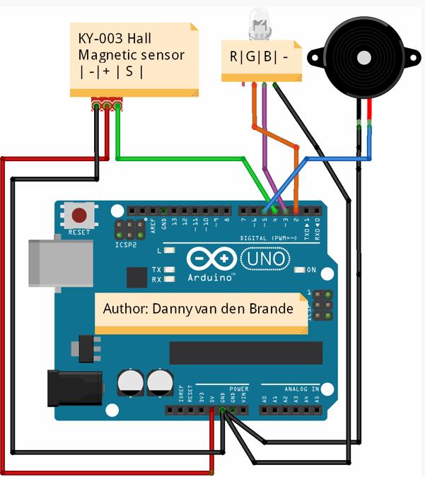
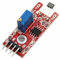
2.06 KY-003 Hall magnetic - Magnetic Hall-Sensor § Hall=pin-4 RGB-LED=Pin-2, 3 Buzzer=pin-5
|
|
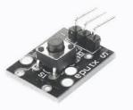
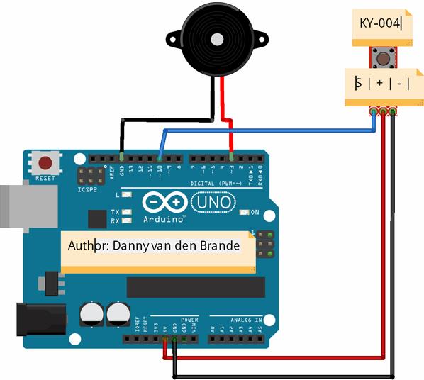
3.02 KY-004 Button - Tast-Schalter § Schalter=pin-10 Buzzer=pin-3
|
|
1.09 KY-005 IR emision - Infrarot-Sender § IR-LED=pin-11 Serial
|
|
1.14 KY-006 Passive buzzer - Piezo-Lautsprecher § Piezo-Ls=pin-8
|
|
1.05 KY-008 Laser emitter - Laser-Transmitter Modul § Emitter=pin-6 Detector=pin-7 Buzzer=pin-8 7-color-LED=pin-4 Relais=pin-5
|
|
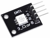
3.07 KY-009 SMD RGB - RGB-LED (SMD) § RGB-LED=pin-9..11
|
|
1.12 KY-010 Light blocking - Gabel-Lichtschranke § Modul=pin-A0 Buzzer=pin-7 RGB-LED=pin-4, 5, 6
|
|
3.09 KY-011 Two-color small - 2-Farben LED 5mm § Duo-LED=pin-10, 11
|
|
1.15 KY-012 buzzer - Active Buzzer Modul § Buzzer=pin-8
|
|
2.13 KY-013 Analog temp - NTC Temperatur-Sensor § Modul=pin-A5
|
|
1.02 KY-013 NTC Temperatur-Sensor § NTC=pin-A0 LCD1602=pin-16, 17
|
|
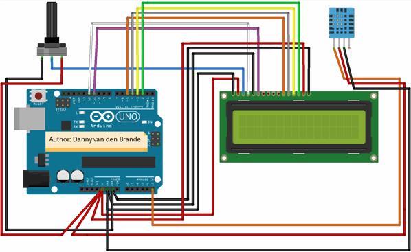
2.02 KY-015 Temp and humidity - Temperatur und Luftfeeuchte-Sensor § DHT-11=pin-A5 LCD1602A=I2C
|
|
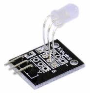
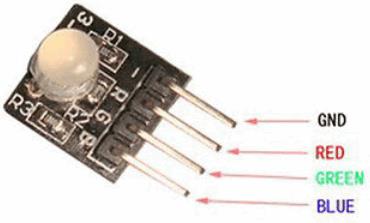
3.10 KY-016 RGB LED - 3-Farben RGB-LED 5mm § RGB-LED=pin-9..11
|
|
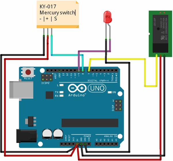
2.03 KY-017 Tilt switch - Quecksilber-Neigungs-Schalter § Schalter=pin-8 LED=pin-9 Relais=pin-7
|
|
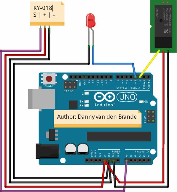
2.05 KY-018 Photoresistor - Dämmerungs-Schalter § LDR05=pin-A0 LED=pin-3 Relais=pin-2
|
|
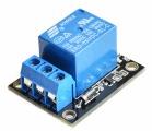
3.06 KY-019 Relay - Relaismodul § Relais=pin-3 Taster=pin-10
|
|
2.12 KY-020 Ball switch - Neigungs-Schalter (Kugelschalter) § Schalter=pin-3 Relais=pin-2
|
|
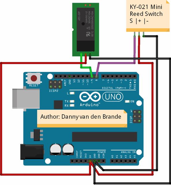
2.01 KY-021 Mini Reed - Mini-Reed-Schalter § Reed=pin-8 Relais=pin-9
|
|
1.08 KY-022 IR receiver - Infrarot-Empfänger § IR-Transistor=pin-4 RGB=pin-6, 7, 8 Buzzer=pin-9 4xRelais=pin-5 pin-10, 11, 12
|
|
2.14 KY-023 JoyStick - XY-Joystick § Modul=pin-A0, A1 RGB-LED=pin-3, 4, 5 Duo-LED=pin-2
|
|
3.03 KY-024 Linear Hall - Linearer Hall-Sensor § Hall=pin-3 LED=pin-13
|
|
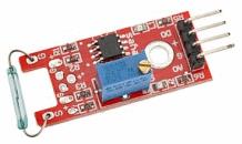
3.04 KY-025 Reed switch - Reed-Schalter § Schalter=pin-3 LED=pin-13
|
|
1.01 KY-026 Flame - Flammen-Sensor § Modul=pin-4 & pin-A0 Buzzer=pin-3 LEDgrün=pin-8 LEDrot=pin-6 Taster=pin-Reset Relais=pin-7
|
|
3.01 KY-027 Light Cup - Quecksilber-Schalter mit LED § Schalter=pin-4..7 2xRelais=pin2, 3
|
|
2.11 KY-028 Digital temp - NTC Temperatur Sensor § Modul=pin-A5
|
|
3.08 KY-029 Two-color small - 2-Farben LED 3mm § Duo-LED=pin-10, 11
|
|
1.11 KY-031 Top module - Erschütterungs-Sensor - Schlag-Sensor-Modul § Modul=pin-4 Buzzer=pin-7 RGB-LED=pin-5, 6
|
|
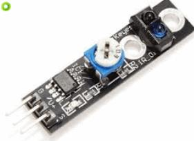
1.10 KY-032 Tracking - IR-Reflex-Sensor - Hindernisvermeidungssensor § Modul=pin-4 Buzzer=pin-3 RGB-LED=pin-5, 6
|
|
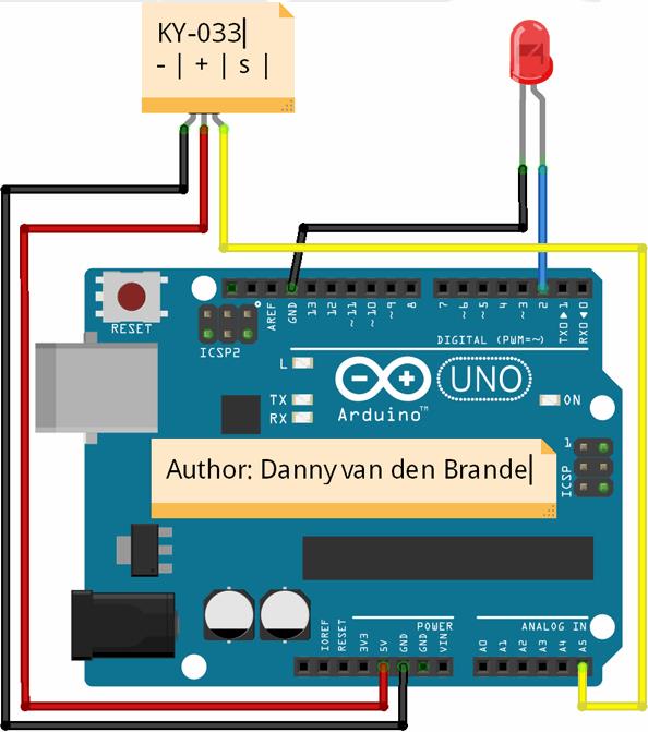
2.13 KY-032 Tracking - Linienverfolgungs-Sensor § Reflex-Sensor=pin-A5 LED=pin-2
|
|
1.04 KY-034 7-color flash - 7-Farben LED-Modul § LED=pin-13
|
|
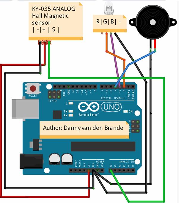
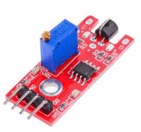
2.07 KY-035 Analog Hall - Analog Magnetic Hall-Sensor § Hall=pin-A0 RGB-LED=pin-2,3 Buzzer=pin-4
|
|
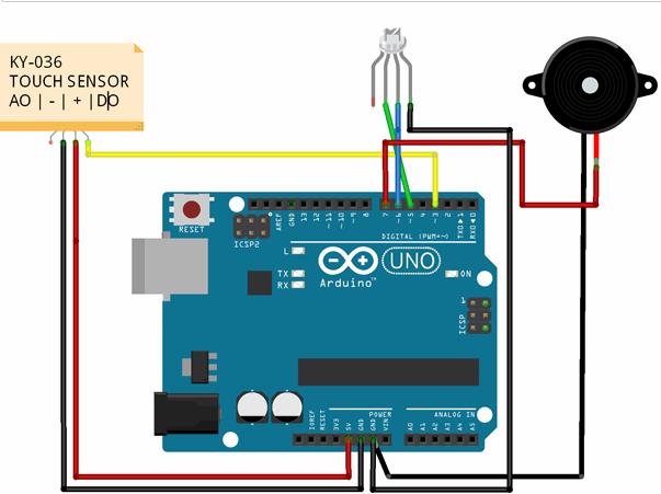
2.08 KY-036 Touch - Berühr-Schalter § Modul=pin-3 RGB-LED=pin-5,6 Buzzer=pin-7
|
|
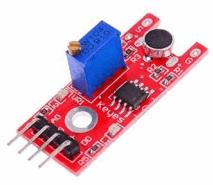
2.09 KY-037 Big sound - ECM-Sensor Dm=10mm § Modul-Analog=pin-A0 Modul-Digital=pin-13
|
|
2.10 KY-038 Small sound - ECM-Sensor Dm=6mm § Modul-Analog=pin-A0 Modul-Digital=pin-13
|
|
3.05 KY-039 Heartbeat - Herzschlag- / Puls-Sensor § Modul=pin-A0 LCD1602A=I2C
|
|
1.13 KY-040 Rotary encoders - Drehimpuls-Geber § Modul=pin-8, 9, RGB-LED=pin-4, 5, 6
|
|
1.03 KY-050 Ultraschall-Semsor - Distanzsensor § HC-SR04=pin-8, 9 LCD1602=pin-2..5
|
|
1.06 KY-999 Laser receiver - Laserempfänger mit LED § Sender=pin-6 Receiver=pin-7 Buzzer=pin-8 7-color-LED=pin-4 Relais=pin-5
|
3.13 KY-052 Druck-Sensor BMP180 § BMP180
Arduino 37-in-1 Sensor kit Module-Verzeichnis
Small passive buzzer module
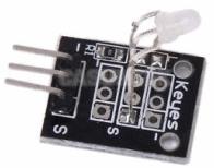
2-color LED module
Hit sensor module
Vibration switch module
Photo resistor module
Key switch module
Tilt switch module
3-color full-color LED SMD module
Infrared emission sensor module
3-color LED module
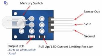
Mercury open optical module
Yin Yi 2-color LED module 3MM
Active buzzer module
Temperature sensor module
Automatic flashing colorful LED module
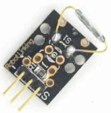
Mini magnetic reed modules
Hall magnetic sensor module
Infrared sensor receiver module
Class Bihor magnetic sensor
Magic light cup module
Rotary encoder module
Optical broken module
Detect the heartbeat module
Reed module
Obstacle avoidance sensor module
Hunt sensor module
Microphone sound sensor module
Laser sensor module
5V relay module
Temperature sensor module
Temperature sensor module
Linear magnetic Hall sensors
Flame sensor module
Sensitive microphone sensor module
Temperature and humidity sensor module
XY-axis joystick module
Metal touch sensor module
http://arduinosensors.nl/index.php?route=product/product&path=62&product_id=101
Inhaltsverzeichnis dieser Seite
2.01 KY-021 Mini Reed - Mini-Reed-Schalter § Reed=pin-8 Relais=pin-9
2.02 KY-015 Temp and humidity - Temperatur und Luftfeeuchte-Sensor § DHT-11=pin-A5 LCD1602A=I2C
2.03 KY-017 Tilt switch - Quecksilber-Neigungs-Schalter § Schalter=pin-8 LED=pin-9 Relais=pin-7
2.04 KY-001 TEMP - Temperatur-Sensor § DS18B20=pin-2 LCD5110=pin-8 bis12
2.05 KY-018 Photoresistor - Dämmerungs-Schalter § LDR05=pin-A0 LED=pin-3 Relais=pin-2
2.06 KY-003 Hall magnetic - Magnetic Hall-Sensor § Hall=pin-4 RGB-LED=Pin-2, 3 Buzzer=pin-5
2.07 KY-035 Analog Hall - Analog Magnetic Hall-Sensor § Hall=pin-A0 RGB-LED=pin-2,3 Buzzer=pin-4
2.08 KY-036 Touch - Berühr-Schalter § Modul=pin-3 RGB-LED=pin-5,6 Buzzer=pin-7
2.09 KY-037 Big sound - ECM-Sensor Dm=10mm § Modul-Analog=pin-A0 Modul-Digital=pin-13
2.10 KY-038 Small sound - ECM-Sensor Dm=6mm § Modul-Analog=pin-A0 Modul-Digital=pin-13
2.11 KY-028 Digital temp - NTC Temperatur Sensor § Modul=pin-A5
2.12 KY-020 Ball switch - Neigungs-Schalter (Kugelschalter) § Schalter=pin-3 Relais=pin-2
2.13 KY-013 Analog temp - NTC Temperatur-Sensor § Modul=pin-A5
2.13 KY-032 Tracking - Linienverfolgungs-Sensor § Reflex-Sensor=pin-A5 LED=pin-2
2.14 KY-023 JoyStick - XY-Joystick § Modul=pin-A0, A1 RGB-LED=pin-3, 4, 5 Duo-LED=pin-2
http://arduinosensors.nl/index.php?route=product/category&path=20&page=2
3.01 KY-027 Light Cup - Quecksilber-Schalter mit LED § Schalter=pin-4..7 2xRelais=pin2, 3
3.02 KY-004 Button - Tast-Schalter § Schalter=pin-10 Buzzer=pin-3
3.03 KY-024 Linear Hall - Linearer Hall-Sensor § Hall=pin-3 LED=pin-13
3.04 KY-025 Reed switch - Reed-Schalter § Schalter=pin-3 LED=pin-13
3.05 KY-039 Heartbeat - Herzschlag- / Puls-Sensor § Modul=pin-A0 LCD1602A=I2C
3.06 KY-019 Relay - Relaismodul § Relais=pin-3 Taster=pin-10
3.07 KY-009 SMD RGB - RGB-LED (SMD) § RGB-LED=pin-9..11
3.08 KY-029 Two-color small - 2-Farben LED 3mm § Duo-LED=pin-10, 11
3.09 KY-011 Two-color small - 2-Farben LED 5mm § Duo-LED=pin-10, 11
3.10 KY-016 RGB LED - 3-Farben RGB-LED 5mm § RGB-LED=pin-9..11
3.11 KY-000 Soil Moisture - Bodenfeuchtesensor § Feuchte=pin-A0 LCD1602A=pin-16, 17 Servo=pin-9
http://arduinosensors.nl/index.php?route=product/category&path=20&page=3
2.01 KY-021 Mini Reed - Mini-Reed-Schalter
//Author: Danny van den Brande, arduinosensors.nl.//Hello world! I made a simple example on the KY-021 mini reed switch.//Do what ever you like with this code! This code will turn on a relay.//In my video i used a lamp, but you can add any device to the relay if you want.//reed switches can be used for a dozen of things but is mostly known for its use//in burglar alarms, and work with a magnetic field.int Relay = 9 ;int MiniReed = 8; int val ;void setup (){ pinMode (Relay, OUTPUT); pinMode (MiniReed, INPUT); //The mini reed switch need to be set as input.}void loop (){ val = digitalRead (MiniReed) ; if (val == HIGH) //change this to LOW if you want the code to work the other way around. { digitalWrite (Relay, HIGH);// turns lamp on } else { digitalWrite (Relay, LOW);// turns lamp off }}
2.02 KY-015 Temp and humidity - Temperatur und Luftfeeuchte-Sensor DHT-11
Sketch für Sensor DHT11 bzw. DHT-11
/*Author: Danny van den Brande, Arduinosensors.nl. BlueCore Tech.Simple Temp and Humidity Sensor with the LCD 1602A.You can also use the I2C for the LCD 1602A i already put the required Lines in the CODE.All you need to do is find the right adress for your I2C @ #define I2C_ADDRin the code you can find the most used adresses. *///#include <Wire.h> Uncomment when using the I2C!//#include <LiquidCrystal_I2C.h> //we use this when we are using a screen with a I2C//Uncomment #include <LiquidCrystal_I2C.h> and remove #include <LiquidCrystal.h> //if you are using a LCD 1602A with a I2C.#include <LiquidCrystal.h> #include <DHT.h> //i2C Adresses: PCF8574 = 0x20, PCF8574A = 0x38,PCF8574AT = 0x3F < the adresses for most used lcd 1602 Lcds.//Uncomment all #define here below when using a I2C.//#define I2C_ADDR 0x3F //<< I2C adress look at the back of you I2C to see which on you have.//#define BACKLIGHT_PIN 3//#define En_pin 2//#define Rw_pin 1//#define Rs_pin 0//#define D4_pin 4//#define D5_pin 5//#define D6_pin 6//#define D7_pin 7//int DHT11Sensor = 7;int DHT11value; #define DHTPIN A5 #define DHTTYPE DHT11 DHT dht(DHTPIN, DHTTYPE);//Uncomment the line LiquidCrystal_I2C and remove LiquidCrystal when using a I2C. LiquidCrystal lcd(12, 11, 5, 4, 3, 2);//<Remove when using the I2C.//LiquidCrystal_I2C lcd(I2C_ADDR, En_pin,Rw_pin,Rs_pin,D4_pin,D5_pin,D6_pin,D7_pin); //<<Uncomment when using the I2C.byte degree[8] ={ B00001100, B00010010, B00010010, B00001100, B00000000, B00000000, B00000000, B00000000,}; void setup(){Serial.begin(9600); lcd.begin(16,2); lcd.clear(); lcd.createChar(0, degree);} void loop(){float h = dht.readHumidity(); float t = dht.readTemperature(); lcd.setCursor(0,0);lcd.print("Temp : ");lcd.print(" ");lcd.setCursor(7,0);lcd.print(t,1);lcd.setCursor(12,0);lcd.write((byte)0);//lcd.print((char)223);// Print degree symbol. lcd.setCursor(0,1);lcd.print("Humid: ");lcd.print(" ");lcd.setCursor(7,1);lcd.print(h,1);lcd.setCursor(12,1);lcd.print("%"); delay(2000);}
2.03 KY-017 Tilt switch - Quecksilber-Neigungs-Schalter
/*Author:Danny van den Brande, Arduinosensors.nl. BlueCore Tech.This example will show you how a Mercury switch works.This example is very basic and easy to understand.It will turn on a relay when tilting the switch.You can add a lamp or any device to the relay. */int BlueLed = 9;int KwikSwitch = 8;int Relay = 7;int val;void setup() {pinMode (BlueLed, OUTPUT);pinMode (Relay, OUTPUT);pinMode (KwikSwitch, INPUT);}void loop() { val = digitalRead (KwikSwitch) ; if (val == HIGH) { digitalWrite (BlueLed, HIGH); digitalWrite (Relay, HIGH); } else { digitalWrite (BlueLed, LOW); digitalWrite (Relay, LOW); } }
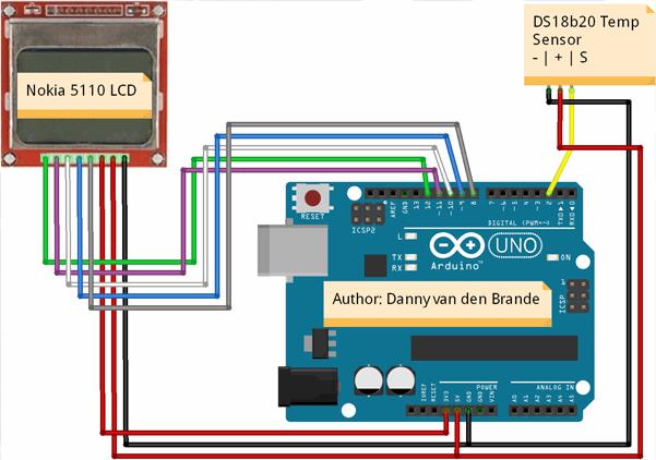
/*Author: Danny van den Brande, ArduinoSensors.nl. BlueCore Tech.Hello world! this is a example project for the DS18b20 on a old Nokia 5110 LCD Display. */#include <OneWire.h>#include <DallasTemperature.h>#include <LCD5110_Graph.h>#define ONE_WIRE_BUS 2LCD5110 lcd(8,9,10,12,11);extern unsigned char SmallFont[];extern unsigned char BigNumbers[];extern uint8_t borderRoundedIcon[];char TempCelciusFahrenheit[6];OneWire oneWire(ONE_WIRE_BUS);DallasTemperature sensors(&oneWire);float tempC = 0;float tempF = 0;void setup(void){ lcd.InitLCD(); sensors.begin();}void loop(void){ lcd.clrScr(); lcd.drawBitmap(0, 0, borderRoundedIcon, 84, 48); sensors.requestTemperatures(); tempC = sensors.getTempCByIndex(0); tempF = sensors.toFahrenheit(tempC); // convertToString(tempF); //these are Fahrenheit, uncomment when using degrees. convertToString(tempC); //These are degrees, comment when using Fahrenheit. lcd.setFont(BigNumbers); lcd.print(TempCelciusFahrenheit,22,14); // You can set position of the text here. lcd.setFont(SmallFont); lcd.print("Temp.Celc.",17,5); //Comment when using Fahrenheit// lcd.print("Temp.Fahr.",17,5); //Uncomment when using Celcius lcd.update(); delay(1000);}void convertToString(float number){ dtostrf(number, 3, 1, TempCelciusFahrenheit);}
2.05 KY-018 Photoresistor - Dämmerungs-Schalter mit LDR05
/*Author: Danny van den Brande, Arduinosensors.nl. BlueCore Tech.In this example we use the Photoresistor as a switch.Its just a basic code, you can adjust the value at the if statement between 0 and 1023. */int Relay = 2;int BlueLed = 3;int Sensor = A0;int sensorValue;void setup() { pinMode(BlueLed, OUTPUT); pinMode(Relay, OUTPUT); pinMode(Sensor, INPUT); Serial.begin(9600);}void loop() { sensorValue = analogRead(Sensor); if(analogRead(1)>200 && analogRead(1)< 1023) { digitalWrite (BlueLed, LOW); digitalWrite (Relay, LOW); Serial.println(sensorValue, DEC); } else { digitalWrite (BlueLed, HIGH); digitalWrite (Relay, HIGH); Serial.println(sensorValue, DEC); } }
2.06 KY-003 Hall magnetic - Magnetic Hall-Sensor
/*Author: Danny van den Brande, Arduinosensors.nl. BlueCore Tech.In this example we use the hall magnetic sensor as a magnetic field detector. A simple but useful code.*/int GreenLed = 2;int BlueLed = 3; int MagneticHallSensor = 4;int Buzzer = 5;int val; void setup (){ pinMode (GreenLed, OUTPUT); pinMode (BlueLed, OUTPUT); pinMode (MagneticHallSensor, INPUT); pinMode (Buzzer, OUTPUT);} void loop (){ val = digitalRead (MagneticHallSensor) ; if (val == LOW) //Set to HIGH if you want the device to work the other way around. { digitalWrite (BlueLed, HIGH); digitalWrite (Buzzer, HIGH); delay(1000); digitalWrite (BlueLed, LOW); digitalWrite (Buzzer, LOW); delay(100); } else { digitalWrite (BlueLed, LOW); digitalWrite (GreenLed, HIGH); delay(1000); digitalWrite (GreenLed, LOW); digitalWrite (Buzzer, LOW); delay(100); }}
2.07 KY-035 Analog Hall - Analog Magnetic Hall-Sensor
/*Author: Danny van den Brande, Arduinosensors.nl. BlueCore Tech.In this example we use the hall magnetic sensor as a magnetic field detector. A simple but useful code.*/int Buzzer = 4; int sensorPin = A0; int GreenLed = 2; int BlueLed = 3; int sensorValue = 0; void setup () {pinMode (BlueLed, OUTPUT);pinMode (GreenLed, OUTPUT);pinMode (Buzzer, OUTPUT);Serial.begin (9600);} void loop () {sensorValue = analogRead (sensorPin);if(analogRead(1)>575 && analogRead(1)< 700) //You can play with these values, open serial //monitor to see value readings. { digitalWrite (BlueLed, HIGH); digitalWrite (Buzzer, HIGH); delay(1000); digitalWrite (BlueLed, LOW); digitalWrite (Buzzer, LOW); delay(100); Serial.println(sensorValue, DEC); } else { digitalWrite (BlueLed, LOW); digitalWrite (GreenLed, HIGH); delay(1000); digitalWrite (GreenLed, LOW); digitalWrite (Buzzer, LOW); delay(100); Serial.println(sensorValue, DEC); } }
2.08 KY-036 Touch - Berühr-Schalter
/*Author: Danny van den brande, Arduinosensors.nl. BlueCore Tech.In this example we use the KY-036 Touch sensor to turn on a led and buzzer. */int GreenLed = 5;int BlueLed = 6;int Buzzer = 7;int TouchSensor = 3; int val;void setup (){pinMode (GreenLed, OUTPUT);pinMode (BlueLed, OUTPUT);pinMode (Buzzer, OUTPUT);pinMode (TouchSensor, INPUT);}void loop (){val = digitalRead (TouchSensor) ;if (val == HIGH) {digitalWrite (BlueLed, HIGH);digitalWrite (GreenLed, LOW);digitalWrite (Buzzer, HIGH);}else{digitalWrite (BlueLed, LOW);digitalWrite (GreenLed, HIGH);digitalWrite (Buzzer, LOW);}}
2.09 KY-037 Big sound - ECM-Sensor 10mm
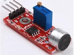
Connecting to the ArduinoPin + to Arduino 5V+Pin - to Arduino -Pin A0 to Arduino pin-A0 (for analog program)Pin D0 to Arduino pin-13 (for digital program)


Example code: Digital output.

int Led = 13 ;// define LED Interface
int buttonpin = 3; // define D0 Sensor Interface
int val = 0;// define numeric variables val

void setup ()
{
  pinMode (Led, OUTPUT) ;// define LED as output interface
  pinMode (buttonpin, INPUT) ;// output interface D0 is defined sensor
}

void loop ()
{
  val = digitalRead(buttonpin);// digital interface will be assigned a value of pin 3 to read val
  if (val == HIGH) // When the sound detection module detects a signal, LED flashes
  {
    digitalWrite (Led, HIGH);
  }
  else
  {
    digitalWrite (Led, LOW);
  }
}


Example Code : analog outputs


int sensorPin = A0; // select the input pin for the potentiometer
int ledPin = 13; // select the pin for the LED
int sensorValue = 0; // variable to store the value coming from the sensor

void setup ()
{
  pinMode (ledPin, OUTPUT);
  Serial.begin (9600);
}

void loop ()
{
  sensorValue = analogRead (sensorPin);
  digitalWrite (ledPin, HIGH);
  delay (sensorValue);
  digitalWrite (ledPin, LOW);
  delay (sensorValue);
  Serial.println (sensorValue, DEC);
}


2.10   KY-038 Small sound - ECM-Sensor 6mm
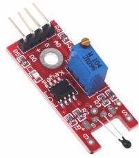
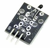
2.11 KY-028 Digital temp - NTC Temperatur Sensor
SIEHE KY-037
SCHEMATIC: Arduino pin analog A5 --> module S (Signal)
Arduino pin GND - module -
Arduino pin 5+ --> middel pin 5V
Dieser Code geben Sie nicht die richtigen Werte, in einem Raum, der Art von ok es eine tempature von 10 C.
Das ist nicht richtig, so dass die Berechnung im Code überprüft werden wird gegeben war.
#include <math.h>
int sensorPin = A5; // select the input pin for the potentiometer

double Thermistor(int RawADC) {
  double Temp;
  Temp = log(10000.0*((1024.0/RawADC-1)));
  Temp = 1 / (0.001129148 + (0.000234125 + (0.0000000876741 * Temp * Temp ))* Temp );
  Temp = Temp - 273.15;            // Convert Kelvin to Celcius
   //Temp = (Temp * 9.0)/ 5.0 + 32.0; // Convert Celcius to Fahrenheit
   return Temp;
}

void setup() {
 Serial.begin(9600);
}

void loop() {
 int readVal=analogRead(sensorPin);
 double temp =  Thermistor(readVal);

 Serial.println(temp);  // display tempature
 //Serial.println(readVal);  // display tempature

 delay(500);
}
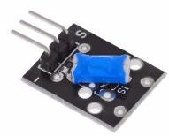
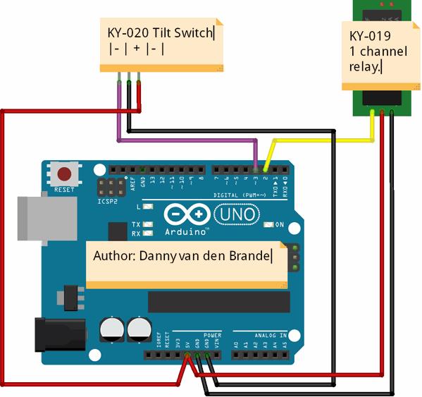
2.12 KY-020 Ball switch - Neigungs-Schalter (Kugelschalter)
/*Author: Danny van den Brande, Arduinosensors.nl. BlueCore Tech.In this example we switch on a light with a relay and the KY-020 Tilt Switch */int Relay = 2;int TiltSwitch = 3; int val ;void setup (){ pinMode (Relay, OUTPUT); pinMode (TiltSwitch, INPUT); Serial.begin(9600);}void loop (){ val = digitalRead (TiltSwitch); if (val == HIGH) { digitalWrite (Relay, HIGH); Serial.print ("Value: ");//You can remove the serial print section. Serial.println (val); delay(100); } else { digitalWrite (Relay, LOW); Serial.print ("Value: ");//You can remove the serial print section. Serial.println (val); delay(100); }}
2.13 KY-013 Analog temp - NTC Temperatur-Sensor
SIEHE
KY-028 Digital temp - NTC Temperatur Sensor
2.13 KY-032 Tracking - Linienverfolgungs-Sensor
SIEHE auf einer anderen Seite
KY-032 Tracking - IR-Reflex-Sensor - Hindernisvermeidungssensor
/*Author: Danny van den Brande, Arduinosensors.nl. Bluecore Techin this example i show you how to use the KY-033 as a white line tracer. */int WhiteLed = 2; int Sensor = A5; int sensorValue = 0; void setup () { pinMode (WhiteLed, OUTPUT); Serial.begin (9600);}void loop () { sensorValue = analogRead (Sensor); if (sensorValue < 50&& sensorValue < 500) { digitalWrite (WhiteLed, HIGH); Serial.println (sensorValue, DEC); } else (sensorValue > 500&& sensorValue > 1023); { digitalWrite (WhiteLed, LOW); Serial.println (sensorValue, DEC); }}
2.14 KY-023 JoyStick - XY-Joystick
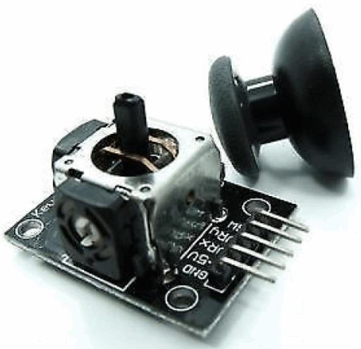
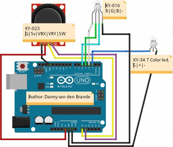
int FlashLed = 2; int RedLed = 3; int GreenLed = 4; int BlueLed = 5; int XVALUE = 0;int YVALUE = 0;int VALUE = 0;void setup() { pinMode(FlashLed, OUTPUT); pinMode(RedLed, OUTPUT); pinMode(GreenLed, OUTPUT); pinMode(BlueLed, OUTPUT); Serial.begin(9600);}void loop() { XVALUE = analogRead(0); Serial.print("X:"); Serial.print(XVALUE, DEC); YVALUE = analogRead(1); Serial.print(" Y:"); Serial.print(YVALUE, DEC); if (XVALUE < 10) { digitalWrite(FlashLed, HIGH); digitalWrite(RedLed, LOW); digitalWrite(GreenLed, LOW); digitalWrite(BlueLed, LOW); Serial.print(" - FlashLed"); } if (XVALUE > 1000) { digitalWrite(FlashLed, LOW); digitalWrite(RedLed, HIGH); digitalWrite(GreenLed, LOW); digitalWrite(BlueLed, LOW); Serial.print(" - RedLed"); } if (YVALUE < 10) { digitalWrite(FlashLed, LOW); digitalWrite(RedLed, LOW); digitalWrite(GreenLed, HIGH); digitalWrite(BlueLed, LOW); Serial.print(" - GreenLed"); } if (YVALUE > 1000) { digitalWrite(FlashLed, LOW); digitalWrite(RedLed, LOW); digitalWrite(GreenLed, LOW); digitalWrite(BlueLed, HIGH); Serial.print(" - BlueLed"); } if((YVALUE<1000 && YVALUE>10) && (XVALUE<1000 && XVALUE>10) ) { digitalWrite(FlashLed, LOW); digitalWrite(RedLed, LOW); digitalWrite(GreenLed, LOW); digitalWrite(BlueLed, LOW); } Serial.println(); delay(100);}
http://arduinosensors.nl/index.php?route=product/category&path=20&page=2
*********************************************************
3.01 KY-027 Light Cup - Quecksilber-Schalter mit LED

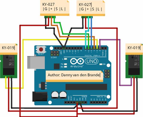
/* * Author: Danny van den brande, Arduinosensors.nl. BlueCore Tech. * This is a simple example on how to use the KY-027 Magic Light * Cup/Mercury Switch. * We are going to use it as some kind of alarm to switch on lamps * when tilting left or right. */int Relay1 = 2;int Relay2 = 3;int MagicLed1 = 5;int MagicLed2 = 6;int MagicCup1 = 7;int MagicCup2 = 4;int MagicCupState1 = 0;int MagicCupState2 = 0;int brightnessLed1 = 0;int brightnessLed2 = 0;void setup (){pinMode (Relay1, OUTPUT);pinMode (Relay2, OUTPUT);pinMode (MagicLed1, OUTPUT);pinMode (MagicLed2, OUTPUT);pinMode (MagicCup1, INPUT);pinMode (MagicCup2, INPUT);}void loop (){tiltLeft();tiltRight();delay(25);} void tiltLeft(){ MagicCupState1 = digitalRead (MagicCup1);if (MagicCupState1 == HIGH && brightnessLed1 != 255){brightnessLed1= 255;digitalWrite(Relay1, HIGH);}else{brightnessLed1 = 0;}analogWrite (MagicLed1, brightnessLed1); digitalWrite(Relay2, LOW);delay(100);}void tiltRight(){ MagicCupState2 = digitalRead (MagicCup2);if (MagicCupState2 == HIGH && brightnessLed2 != 255){brightnessLed2 = 255;digitalWrite(Relay2, HIGH);}else{brightnessLed2 = 0;}analogWrite(MagicLed2, brightnessLed2);digitalWrite(Relay1, LOW);delay(100);}
3.02 KY-004 Button - Tast-Schalter
//Hello world! This time i made a very simple example on how to use a button.//the KY-004 button module is very easy to use and requires just a small code.int Buzzer = 3 ;int Button = 10; boolean val ;// here i set up the tones, you can change them @ void loop.int tones[] = {261, 277, 293, 311, 329, 349, 369, 392, 415, 440, 466, 493, 523 ,554};// 1 2 3 4 5 6 7 8 9 10 11 12 13 14// You can add more tones but i added 14. Just fill in what tone you would like to use, //@ void loop you see " tone(Buzzer, tones[12]); " below, digitalWrite(Buzzer, HIGH);// here you can change the tones by filling in a number between 1 and 14void setup (){ pinMode (Buzzer, OUTPUT); pinMode (Button, INPUT); //Part of buzzer tones for (int i = 0; i < Buzzer; i++) ; }void loop (){ val = digitalRead (Button); if (val == 0) { digitalWrite (Buzzer, HIGH); tone(Buzzer, tones[14]); } else { digitalWrite (Buzzer, LOW); noTone(Buzzer); }}
3.03 KY-024 Linear Hall - Linearer Hall-Sensor
int Led = 13 ;/ / define LED Interface
int buttonpin = 3; / / define the linear Hall magnetic sensor interface
int val ;/ / define numeric variables val
void setup ()
{
pinMode (Led, OUTPUT) ;/ / define LED as output interface
pinMode (buttonpin, INPUT) ;/ / define linear Hall magnetic sensor output interface
}
void loop ()
{
val = digitalRead (buttonpin) ;/ / digital interface will be assigned a value of 3 to read val
if (val == HIGH) / / When the linear Hall sensor detects a magnetic signal, LED flashes
{
digitalWrite (Led, HIGH);
}
else
{
digitalWrite (Led, LOW);
}
}
3.04 KY-025 Reed switch - Reed-Schalter
int Led = 13 ;/ / define LED Interface
int buttonpin = 3; / / define the Reed sensor interfaces
int val ;/ / define numeric variables val
void setup ()
{
pinMode (Led, OUTPUT) ;/ / define LED as output interface
pinMode (buttonpin, INPUT) ;/ / output interface as defined Reed sensor
}
void loop ()
SunFounder{
val = digitalRead (buttonpin) ;/ / digital interface will be assigned a value of 3 to read val
if (val == HIGH) / / When the Reed sensor detects a signal, LED flashes
{
digitalWrite (Led, HIGH);
}
else
{
digitalWrite (Led, LOW);
}
}
3.05 KY-039 Heartbeat - Herzschlag- / Puls-Sensor
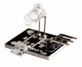
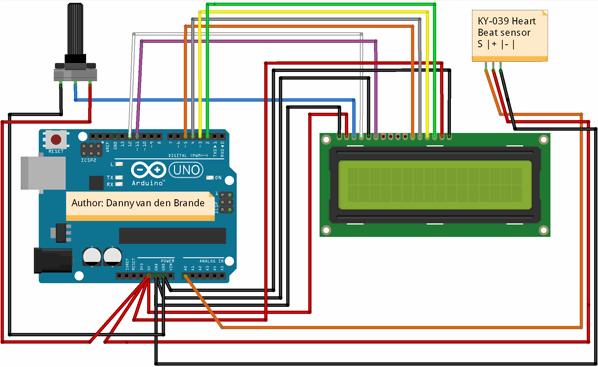
/*This example will show you how to use the KY-039 heart bear sensor.Its a simple basic heart beat monitor with a LCD1602A. In this example i did not use a I2C for those who dont have it. */#include <Wire.h>#include <LiquidCrystal.h> //#include <LiquidCrystal_I2C.h>//uncomment when using a I2C//LiquidCrystal_I2C lcd(0x27, 2, 1, 0, 4, 5, 6, 7, 3, POSITIVE);// Uncomment when using a I2C//make sure you set the right adress. here are the most common ones.//PCF8574 = 0x20, PCF8574A = 0x38, PCF8574AT = 0x3F.LiquidCrystal lcd(12, 11, 5, 4, 3, 2); double alpha=0.75; int period=20; double refresh=0.0; void setup(void){ pinMode(A0,INPUT); lcd.begin(16,2);// lcd.backlight(); //Uncomment when using a I2C lcd.clear(); lcd.setCursor(0,0);}void loop(void){ static double oldValue=0; static double oldrefresh=0; int beat=analogRead(A0); double value=alpha*oldValue+(0-alpha)*beat; refresh=value-oldValue; lcd.setCursor(0,0); lcd.print(" Heart Monitor "); lcd.setCursor(0,1); lcd.print(" "); lcd.setCursor(0,1); lcd.print(beat/10); oldValue=value; oldrefresh=refresh; delay(period*10); }
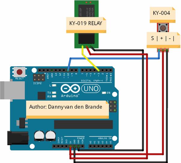
3.06 KY-019 Relay - Relaismodul
/*Author: Danny van den Brande, Arduinosensors.nl. BlueCore Tech.In this example i show you how to use the KY-019 Relay with the KY-004 button module.I attached a 12v alarm siren with strobe to the relay in the video but you can add anything you like offcourse. the Idea now is thatit is functioning as a alarm/panic alarm that can only be turned off when reset.If you want it to work otherwise you need to Uncomment the commented part in the void loop section of the code.*/int Relay = 3;int Button = 10;boolean val;void setup() { pinMode(Relay, OUTPUT); pinMode(Button, INPUT); }void loop() { val = digitalRead (Button); if (val == 0) { digitalWrite (Relay, HIGH);// } //Uncomment if you want the relay only// else //to be on when holding the button.// { //now the alarm need to be reset to turn it off.// digitalWrite (Relay, LOW); }}
3.07 KY-009 SMD RGB - RGB-LED (SMD)
SCHEMATICSince you can't connect the led's directly to the Arduino you will need resistors!!Arduino pin 9 --> 180 Ohm resistor --> Pin 'Red' of KY-009 moduleArduino pin 10 --> 100 Ohm resistor --> Pin 'Green' of KY-009 moduleArduino pin 11 --> 100 Ohm resistor --> Pin 'Blue' of KY-009 moduleArduino GND --> pin '-' of KY-009 module
int redpin = 11; // select the pin for the red LED
int bluepin = 10; // select the pin for the blue LED
int greenpin = 9; // select the pin for the green LED
int val=0;
void setup () {
  pinMode (redpin, OUTPUT);
  pinMode (bluepin, OUTPUT);
  pinMode (greenpin, OUTPUT);
  Serial.begin (9600);
}

void loop () {
  for (val=255; val>0; val--)
  {
    analogWrite (11, val);
    analogWrite (10, 255-val);
    analogWrite (9, 128-val);
    delay (1);
  }
  for (val = 0; val <255; val++)
  {
    analogWrite (11, val);
    analogWrite (10, 255-val);
    analogWrite (9, 128-val);
    delay (1);
  }
  Serial.println (val, DEC);
}
3.08 KY-029 Two-color small - 2-Farben LED 3mm
SCHEMATIC:
Arduino pin 10 --> resistor 330 Ohm --> Signal pin of the moduleArduino pin 11 --> resistor 330 Ohm --> Middel pin of the moduleArduino GND --> module -/GND
int redpin = 11; // select the pin for the red LED
int greenpin = 10; // select the pin for the green LED
int val;
void setup () {
   pinMode (redpin, OUTPUT);
   pinMode (greenpin, OUTPUT);
}
void loop () {
   for (val = 255; val> 0; val--)
      {
      analogWrite (greenpin, val);
      analogWrite (redpin, 255-val);
      delay (15);
   }
   for (val = 0; val <255; val++)
      {
      analogWrite (greenpin, val);
      analogWrite (redpin, 255-val);
      delay (15);
   }
}
3.09 KY-011 Two-color small - 2-Farben LED 5mm
SIEHE KY-029
3.10 KY-016 RGB LED - 3-Farben RGB-LED 5mm
SCHEMATIC:
Arduino pin 11 --> Pin R moduleArduino pin 10 --> Pin G moduleArduino pin 9 --> Pin B moduleArduino pin GND --> Pin - moduleSie irgendwelche Widerstände brauchen nicht, diese bereits auf dem Modul enthalten
//KY016 3-color LED module
int redpin = 11; // select the pin for the red LED
int bluepin = 10; // select the pin for the blue LED
int greenpin = 9 ;// select the pin for the green LED
int val;
void setup () {
  pinMode (redpin, OUTPUT);
  pinMode (bluepin, OUTPUT);
  pinMode (greenpin, OUTPUT);
  Serial.begin (9600);
}
void loop ()
{
  for (val = 255; val> 0; val --)
  {
    analogWrite (11, val);
    analogWrite (10, 255-val);
    analogWrite (9, 128-val);
    delay (10);
    Serial.println (val, DEC);
  }
  for (val = 0; val <255; val ++)
  {
    analogWrite (11, val);
    analogWrite (10, 255-val);
    analogWrite (9, 128-val);
    delay (10);
    Serial.println (val, DEC);
  }
}
3.11 KY-000 Soil Moisture - Bodenfeuchtesensor
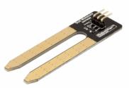
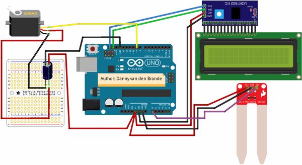
//author:danny van den brande, arduinosensors.nl. BlueCore Tech.//This code is created as a example on how to build a automatic watering plant system with a servo. #include <Wire.h>#include <LCD.h>#include <LiquidCrystal_I2C.h>#include <Servo.h>//Most common adresses PCF8574 = 0x20, PCF8574A = 0x38,PCF8574AT = 0x3F //PCF8574T = 0x27 #define I2C_ADDR 0x27 #define BACKLIGHT_PIN 3#define En_pin 2#define Rw_pin 1#define Rs_pin 0#define D4_pin 4#define D5_pin 5#define D6_pin 6#define D7_pin 7int servoPin = 9;int SensorPin = A0; int SensorValue;Servo myservo; int pos = 90; LiquidCrystal_I2C lcd(I2C_ADDR, En_pin,Rw_pin,Rs_pin,D4_pin,D5_pin,D6_pin,D7_pin);void setup() { Serial.begin(9600); pinMode(SensorPin, INPUT); lcd.begin (16,2); lcd.setBacklightPin(BACKLIGHT_PIN,POSITIVE); lcd.setBacklight(HIGH); lcd.print(" BlueCore Tech "); lcd.setCursor(0,1); lcd.print("Moisture sensor "); delay(5000); lcd.clear(); myservo.attach(servoPin); } void loop() { SensorValue = analogRead(SensorPin); Serial.println (SensorValue); lcd.setCursor(0,0); lcd.print(" Vochtigheid "); lcd.setCursor(0,4); lcd.print(""); lcd.print(SensorValue/10.6); delay(2000); lcd.setCursor(0,4); lcd.clear(); lcd.setCursor(0,4); lcd.print(SensorValue/10.6); if(analogRead(1)<550) { pos = 180; } else { pos = 60 ;} myservo.write(pos); delay(15); }
Quelle.
http://arduinosensors.nl/index.php?route=product/category&path=20&page=3
DIN A4 ausdrucken
*********************************************************
Impressum: Fritz Prenninger, Haidestr. 11A, A-4600 Wels, Ober-Österreich, mailto:[email protected]
ENDE
|
