|
http://sites.schaltungen.at/ewb-v5-12/multisim/grundlagen
Wels, am 2015-04-01BITTE nützen Sie doch rechts OBEN das Suchfeld [ ] [ Diese Site durchsuchen]DIN A3 oder DIN A4 quer ausdrucken ********************************************************************************** DIN A4 ausdrucken
*********************************************************
EWB Electronics Workbench Multisim
Hausarbeiten zu Grundlagen der Leistungselektronik Table of Contents
Power Electronics Fundamentals1. - AC to DC Power - Rectifiers
Publish Date: Nov 08, 2013 | 2 Bewertung(en) | 5,00 von 5 |
Overview
The National Instruments Power Electronics Fundamentals series is designed to provide an overview of power electronics concepts used in research and taught throughout worldwide institutions.
Using advanced simulation models and analyses used in industry, but wrapped in an intuitive, pedagogical environment Multisim enables students to characterize power circuits concepts before the laboratory. The power capabilities of Multisim means that students have access to the same technology that they will use for research and industry to prototype power electronics circuit designs. However in learning power electronics in a simulated environment optimized for education, students have the ability to experiment safely before the laboratory. Table of ContentsRectification systems are primarily designed for converting sinusoidal AC input signals into a DC voltage signals. They are most commonly used in domestic power supplies and power transmission systems. Single wave rectification can be achieved by using either a half wave or full wave rectification circuit.
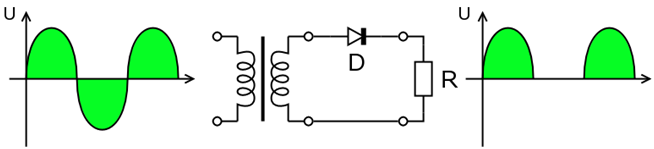
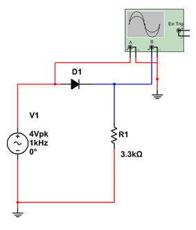
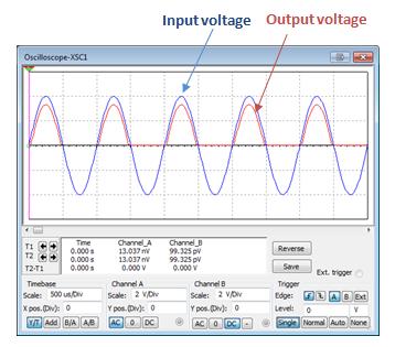
1. Half Wave RectifierHalf-wave rectification systems utilise a single diode, removing half of the sinusoidal source. This produces a single directional signal with a pulsating characteristic.
As a result of the heavy pulsating nature of the signal, more filtering is required to eliminate any harmonies from the AC source and provide a constant DC signal. The efficiency of the half wave rectifier is also limited because only half the sinusoidal waveform is being converted to the DC signal. Losing this half of the signal can be comparable to losing energy..
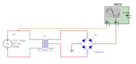
2. Full Wave RectifierFull-wave (full bridge) rectifiers construct a bridge of diodes to convert the whole of the input voltage to one of constant polarity. This is more efficient than the half wave rectifier as it allows both the positive and negative components of the input voltage to be utilised in building the DC voltage.
Once the signal has a single polarity we can apply a simple filter to provide a DC voltage source. This filter applies a smoothing effect allowing the DC output to be maintained.
3. Tutorial QuestionsWhy is it important to select an appropriate capacitor value? What is the effect of using a larger or a smaller capacitor? The bridge circuit above provides us with a positive DC voltage, using NI Multisim identify how this can be modified to develop a negative DC voltage level? 2. - DC to AC Power - Inverters
Publish Date: Nov 05, 2013 | 2 Bewertung(en) | 5,00 von 5 |
Overview
The National Instruments Power Electronics Fundamentals series is designed to provide an overview of power electronics concepts used in research and taught throughout worldwide institutions.
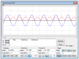
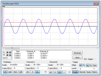
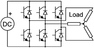
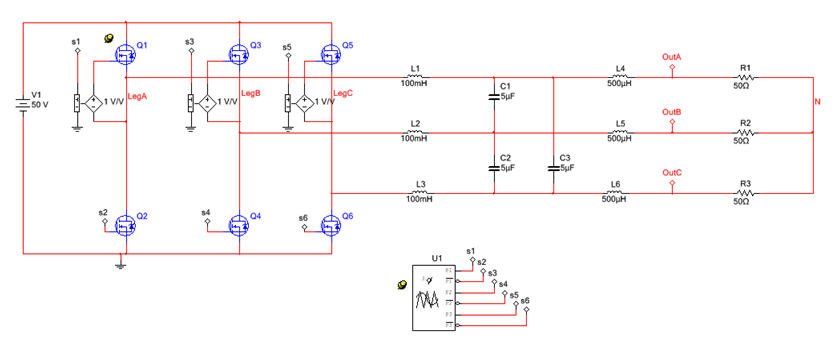
Using advanced simulation models and analyses used in industry, but wrapped in an intuitive, pedagogical environment Multisim enables students to characterize power circuits concepts before the laboratory. The power capabilities of Multisim means that students have access to the same technology that they will use for research and industry to prototype power electronics circuit designs. However in learning power electronics in a simulated environment optimized for education, students have the ability to experiment safely before the laboratory. 1. Three Phase Inverter
2. Transient AnalysisNI Multisim comes with a range of pre-built analysis models. The transient analysis allows us to understand the operation of the inverter and how this leads to the development of the AC signal. The analysis models built into Multisim allows for the characterization of circuits ensuring the optimum circuit design is chosen. The analysis results are based on the industry standard SPICE simulation models, more details of which can be found within the SPICE Simulation Fundamentals Whitepaper series. 3. - DC to DC Power - Regulators
Publish Date: Okt 04, 2013 | 0 Bewertung(en) | 0,00 von 5 |
Overview
The National Instruments Power Electronics Fundamentals series series is designed to provide an overview of power electronics concepts used in research and taught throughout worldwide institutions.
Using advanced simulation models and analyses used in industry, but wrapped in an intuitive, pedagogical environment Multisim enables students to characterize power circuits concepts before the laboratory. The power capabilities of Multisim means that students have access to the same technology that they will use for research and industry to prototype power electronics circuit designs. However in learning power electronics in a simulated environment optimized for education, students have the ability to experiment safely before the laboratory. Table of ContentsWhen considering DC to DC power electronics we are referring mainly to the conversion of one DC voltage to another DC voltage. There are different options for achieving this that vary in complexity and efficiency.
1. Potential DividerA very simple example of regulating voltage is with a potential divider.
However the output across a voltage divider is not constant and varies according to the load. To be effective, changes in the output current must remain small in comparison to the input current. This highlights the inefficiency of this technique as the input current is dissipated as heat. An example of a potential divider is a potentiometer.
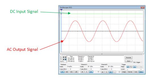
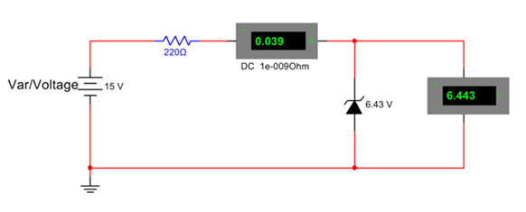
2. Zener Diode RegulatorWe can improve on the potential divider method by using a zener diode. A zener diode allows current to flow in one direction as well as in the reverse direction when the voltage is above a certain breakdown voltage. The diode is setup so that it operates in reverse bias and conducts when the reverse bias breakdown voltage is met. In Multisim we can easily measure the regulated output using Virtual Multimeter Instrument whilst also monitoring the current flow.
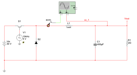
3. Power SwitchingThe buck converter is a form of power switch which dramatically increases the efficiency of the regulator circuit. Its core functionality is built upon switching a voltage to control the output voltage allowing us to step down the input voltage to that needed by the output. A capacitor is required to smooth the output voltage and remove the steps created by the switching.
To achieve this, a Pulse Width Modulated (PWM) signal is used to control the switching of the voltage allowing regulation of the output voltage. When the switch is closed, the inductor will begin to charge and there will be a voltage drop across it causing the output voltage to drop. When the switch is open, the charge within the inductor is released, supplying the output voltage. Below is an example of a simple Buck Converter. A PWM signal is being used to control the switch, allowing the charge in the inductor to build up. Care needs to be taken when selecting the most suited frequency for the PWM signal in order to maintain the required DC voltage level.
To help with determining the correct frequency and component values, Multisim provides interactive components which are capable of having their parameters changed during execution. The use of interactive components allows us to adjust the duty cycle, impedance and resistance during simulation.
The example above shows an open loop implementation of a buck converter. This can be taken a stage further and translated into a closed loop system by taking the output voltage and comparing it to a reference voltage to produce the appropriate PWM signal for the switch. This can be fully modelled in Multisim alongside LabVIEW using co simulation.
Multisim gives you the tools to simulate a schematic prior to the circuit creation whilst LabVIEW assists in creation of the FPGA code. Co-simulation allows these two systems to be integrated allowing full testing of the power switch prior to deployment. You can learn more about co-simulation in Simulation Fundamentals: Cosimulation In NI Multisim tutorial.
4. Tutorial QuestionsWhat happens to the zener voltage if a minimum value of reverse current is being reached and what if the reverse current exceeds its maximum? What is the disadvantage of a zener diode regulator? Here we have an example of a Buck Converter, research and gain an understanding through Multisim of a Boast Converters operation . 4. - Multisim Power Components
Publish Date: Okt 04, 2013 | 1 Bewertung(en) | 5,00 von 5 |
Overview
The National Instruments Power Electronics Fundamentals series series is designed to provide an overview of power electronics concepts used in research and taught throughout worldwide institutions.
Using advanced simulation models and analyses used in industry, but wrapped in an intuitive, pedagogical environment Multisim enables students to characterize power circuits concepts before the laboratory. The power capabilities of Multisim means that students have access to the same technology that they will use for research and industry to prototype power electronics circuit designs. However in learning power electronics in a simulated environment optimized for education, students have the ability to experiment safely before the laboratory. Table of ContentsMultisim is packed with a range of components, the building blocks of any power circuit. This section introduces the major components in greater detail.
1. TransformersThis component is based on a general model that can be customized for different applications. It is implemented using a conceptual magnetic core and coreless coil building blocks, together with resistors and inductors. Using this transformer, you can model physical effects such as nonlinear magnetic saturation, primary and secondary winding losses, primary and secondary leakage inductances, and core geometric size .The transformer also allows the modeling of multiple windings. The options for configuration and personalization makes Multisim an incredibly versatile tool, introducing students to components and models used widely in industry.
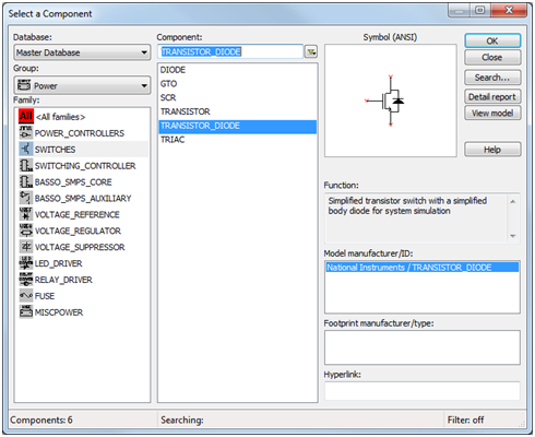
2. SwitchesMultisim’s database include a variety of models for MOSFET and IGBT switches from leading semiconductor manufacturers such as International Rectifier and Texas Instruments. The models are provided by the manufacturer and validated by the Multisim R&D team. Strong relationships are forged between these companies and National Instruments, enhanced by constant communication and trust. These relationships act to continuously improve on Multisim’s database of models, bettering the quality of the product as a whole. Examples of these switches are under the transistors group in Multisim’s database. In addition, Multisim includes generic models for MOSFET switches and basic IGBTs. These components model transistors for system-level simulations in case manufacturer models are not available. Some transistors include a body diode which is based on a simple two-line segment I/V curve.
In addition to the MOSFET generic models, Multisim includes models for Silicon Controlled Rectifiers (SCR), and Gate Turn Off (GTO) switches. With these components, you could accurately simulate your AC control or high-power rectification circuit performance.
3. Gate DriversMultisim’s library is updated with a variety of gate driver components necessary for use with any power switches. The most complicated models are from ON Semiconductor and International Rectifier.
4. Passive Components (RLC)Parasitic behavior of passive components plays an important role in the performance of power circuits. This is why in Multisim components have been created to model parasitics of resistors, capacitors, and inductors.
5. Motors
Many engineers working on electro-mechanical systems find it challenging to predict the electric circuit performance with mechanical parts such as DC machines, stepper motors, and induction machines. To complete the power electronic solution commonly used to drive motors that draw very high current or fed by 3-phase generators, Multisim includes components that models for such mechanical parts of the system. The component group Electro_Mechanical in Multisim’s database contains models for machines, speed sensors, motion controllers, and other parts that could be used for this purpose.
5. Power Electronics Homework Problemshttp://www.ni.com/white-paper/14742/en/
Publish Date: Okt 04, 2013 | 0 Bewertung(en) | 0,00 von 5 |
Overview
The Power Electronics Homework circuits series provides a broad selection of over 30 power electronics circuits which can be used for class demonstrations and homework tutorials. The examples range from power electronic fundamentals to more advance power electronic concepts. This free to use set of circuits provides a starting point to for educators to show key concepts that students need to understand as part of any college or university power electronics course. Circuits are based upon core topics from the Fundamentals of Power Electronics book by Robert W. Erickson and Fragan Maksimovié.
The tutorials are divided into 5 chapters including AC fundamentals and power electonics control systems. More details on the core knowledge behind these examples is avalaible within the Power Electronics Fundamentals Series. Table of Contents
|
MultiSIM >