Startseite

http://sites.schaltungen.at/arduino-uno-r4/

http://www.linksammlung.info/

http://www.schaltungen.at/

                                                                                        Wels, am 2016-06-12

BITTE nützen Sie doch rechts OBEN das Suchfeld  [                                                              ] [ Diese Site durchsuchen]

DIN A3 oder DIN A4 quer ausdrucken
*******************************************************************************I**
DIN A4  ausdrucken   siehe
********************************************************I*
~015_b_PrennIng-a_arduino.uno.r4- (xx Seiten)_1a.pdf

Untergeordnete Seiten (2):

      ACHTUNG: Nur die STARTSEITE elektor UNO R4
     alle die anderen Seiten alles ARDUINO UNO Rev.3


                   STARTSEITE
                                               elektor UNO R4
              veröffentlicht in elektor Heft 6/2016 auf Seite 40 (16-06s40)


KURZBESCHREIBUNG
Der Nachfolger des populären Arduino Uno R3 mit dem neuen Mikrocontroller ATmega328PB
bietet noch mehr Schnittstellen für noch mehr Möglichkeiten!


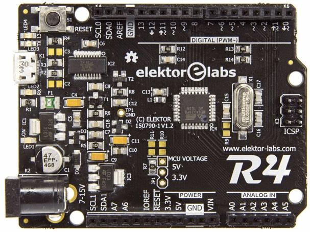
Elektor Uno R4

Vier Pins machen den kleinen Unterschied


Wenn ein Hersteller eine B-Version eines bestehenden Produkts auf den Markt bringt, sind die Unterschiede in der Regel marginal.
Nicht so beim ATmega328P, dem Controller im Herzen des Arduino Uno R3.
Das B-Upgrade verfügt über neue/mehr Peripherie, zum Beispiel einen zweiten UART und mehr PWM-Ausgänge.
Rund um den Chip haben wir daher ein neues Uno-Board gebaut.
Hier kommt der Elektor Uno R4


Quelle:

https://www.elektormagazine.de/magazine/elektor-201606/29017


MIKROCONTROLLER  ATmega328pb


elektor 150790-11


Normalerweise sind die Unterschiede eher klein, wenn ein Hersteller eine B-Version eines Produkts auf den Markt bringt – dies trifft aber nicht auf Atmels neuen Mikrocontroller ATmega328PB zu, dessen Vorgänger ATmega328P unter anderem im Arduino Uno R3 steckt.
Elektor Uno R4 bietet nun diesen neuen verbesserten Mikrocontroller ATmega328PB, der mit vielen zusätzlichen Features auftrumpft.

Der größte Unterschied zwischen Elektor Uno R4 und seinem Vorgänger-Release R3 sind vier extra Pins am Steckverbinder „Power“ sowie sein zweiterUSART. Elektors Uno R4 verfügt über zwei USARTs, was das Debugging und die Software-Entwicklung sehr vereinfacht. Darüber hinaus verfügt der Elektor Uno R4 über einen 4-bit-Port E, ein zweites I²C- plus ein zweites SPI-Interface, ein USB-Interface nun auf Basis eines FTDI-Chips (vereinfacht die Firmware), zwei zusätzliche analoge Eingänge, einen Ausgang für den analogen Komparator, neun PWM-Kanäle, zwei zusätzliche 16-bit-Timer und einen OCM (Output Compare Modulator). Dank seines PTC (Peripheral Touch Controller) kann bei dieser MCU jeder I/O-Pin als touch-sensibler Eingang verwendet werden, ohne dass dazu zusätzliche Hardware erforderlich wäre. Außerdem kann das Board jederzeit aufgrund seiner einzigartigen ID identifiziert werden.

Ein Board-Paket (für Windows) mit einem neuen Compiler und verbesserten Libraries erlaubt die nahtlose Integration des neuen Release R4 in der aktuellen Arduino-IDE.

• ATmega328PB @ 16 MHz
• 2x UART
• 2x I²C
• 2x SPI
• 9 PWM-Ausgänge
• 8 analoge Eingänge
• 24 GPIO-Pins
• 5-V- und 3,3-V-Spannungsregler auf der Platine
• Arduino-kompatible Board-Anschlüsse
• Open-Source- und Open-Hardware-Design

  Arduino Uno R3 Elektor Uno R4
Microcontroller ATmega328P ATmega328PB
Operating Voltage 5 V 5 V or 3.3 V
MCU Power Disconnectable no yes
Input Voltage (recommended) 7-12 V 7-12 V
Input Voltage (limit) 6-20 V 6-20 V
Digital I/O Pins 14 18
PWM Digital I/O Pins 6 9
Analog Input Pins 6 8
Serial Ports (USART) 1 2
I²C 1 2
SPI (not USART) 1 2
Timers 3 5
Analog Comparator Output 1
Output Compare Modulator 1
Input Compare Channels 1 3
Unique ID 1
Peripheral Touch Controller 1
USB connector B Micro B
DC Current per I/O Pin 20 mA 20 mA
DC Current for 3.3 V Pin 50 mA 250 mA
Flash Memory 32 KB 32 KB
Flash Memory for Bootloader 0.5 KB 0.5 KB
SRAM 2 KB 2 KB
EEPROM 1 KB 1 KB
Clock Speed 16 MHz 16 MHz
Length 68.6 mm 68.6 mm
Width 53.4 mm 53.4 mm


Elektor Uno R4

Der Nachfolger des populären Arduino Uno R3 mit dem neuen Mikrocontroller ATmega328PB bietet noch mehr Schnittstellen für noch mehr Möglichkeiten!


Preis: 38,20 € (inkl. Versand)

Deal-Preis: 26,95 € (frei Haus)


Quelle:

https://www.elektor.de/elektor-uno-r4?utm_source=Elektor+Deutschland&utm_campaign=65891cf6a4-07juni2016_Bestsellers_2016_DE_6_6_2016&utm_medium=email&utm_term=0_7096e266f6-65891cf6a4-240392517&mc_cid=65891cf6a4&mc_eid=1b16d56976


*********************************************************

Elektorino Uno R4 [150790]


Status:: Abgeschlossen 
 
 6386 
 
 37 
   
 2
5 votes
vote now! 
 2. März 2016, Latest update: 29. April 2016
prototype-1s.jpg

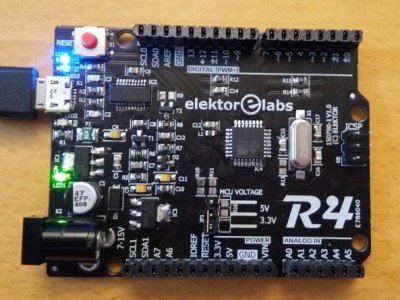
This board is an evolution of the Arduino Uno R3 board. Identical form factor as the Uno but based on the ATmega328PB-AU, this board has much more features than the Uno. Because it is backwards compatible you can think of it as revision 4 of the Uno, which is why we called it the R4.

The circuit of the R4 is pretty close to the Uno. One of the main differences is the USB-to-serial converter for which I used an FTDI chip instead of another AVR. This saves on firmware/driver maintenance & device programming. The power supply is a bit stronger than on the Uno and of course we provided four extra connector pins to accomodate Port E of the ATmega328PB.

Here is a table that shows the main differences between the R3 and the R4.  

  Arduino Uno R3 Elektor Uno R4
USART 1 2
SPI 1 (2 counting USART) 2 (4 counting USART)
I2C 1 2
GPIO 20 24
Analog in 6 8
PWM 6 9
Timer 3 5
OCM - 1

There are some more differences, like the touch controller. Check the datasheet for details.

Drawing up the schematic was easy enough, the hard work is in the software. Because the Arduino IDE does not know about the ATmega328PB I had to build a Boards Package that provides the toolchain. How to do this properly is unfortunately not very well documented, making this a complicated task. Also the SPI and Wire libraries had to be modified to support multiple peripherals. More details about the IDE integration can be found in the Elektor Magazine article published in June 2016.

Note that this Boards Package is intended for Windows only, Linux and Mac users can use it in a virtual machine. To port the package to Linux and Mac, the toolchain avr-gcc v4.9.2 must be replaced by a version compiled for Linux/Mac. The Boards Package can be downloaded from the Elektor.Labs space at GitHub.

Installation

Use the Arduino IDE (v1.6.6 or higher, do not use an IDE from arduino.org) Boards Manager to install this package, as follows:

  1. Open the Arduino IDE's Preferences dialog: File -> Preferences
  2. Add the URL https://raw.githubusercontent.com/ElektorLabs/arduino/master/package_elektor_boards_index.json to the edit box "Additional Boards Manager URLs". (It is possible to have multiple URLs as long as you separate them with commas.) This URL is long and finishes with "json", make sure you copy all of it. You can also copy it from here.
  3. Open the IDE's Boards Manager: Tools -> Board -> Boards Manager
  4. As Type (upper left corner) select Contributed. You should now see at least one entry for Elektor boards.
  5. Click on the entry that you want to install to make the install button appear.
  6. Click the Install button to install the boards.
  7. Close the dialog when done.
  8. Now when you open the available boards list (Tools -> Board) there will be a header "Elektor Labs" followed by the Elektor boards. Choose the one you need.

Note that I use the IDE 1.6.7 for Windows, Arduino IDE 1.6.8 should be avoided because it has a serial port issue.

Now that I have the R4 properly integrated in the Arduino IDE, I find that I use it all the time while my "old-skool" R3s are gathering dust. Especially the R4's second serial port is really handy and makes debugging sketches much easier. Also, using it in 3V3 mode saves a lot of hassle with level shifters. Officially the MCU is not specified for 3V3 @ 16 MHz, but for me it works fine. If it doesn't it is easy enough to replace the crystal by an 8 MHz one (and replace the bootloader!).

New peripherals in sketches

The Elektor Uno R4 has more hardware peripherals than the R3 and so the Arduino libraries have been upgraded to support them. In your sketches you can now use:

  • Serial and Serial1 
  • I2C0 and I2C1 (include the Wire library), I2C defaults to I2C0
  • SPI0 and SPI1 (include the SPI library), SPI defaults to SPI0
  • digitalRead/Write now also work on pins 20 to 23 (port E)
  • analogWrite now also works on pins 0, 1 and 2
  • analogRead accepts A6 and A7


Quelle:

https://www.elektormagazine.de/labs/elektorino-uno-r4-150790


*********************************************************

STÜCKLISTE


1 0 Ω R7
2 27 Ω R2, R3
3 1 kΩ R1, R4, R5, R12, R13, R14
4 10 kΩ R6, R8
5 0 Ω R9, R10, R11
6

7 Capacitor (0805)
8 22 pF C16, C17
9 47 pF C2, C3
10 100 nF C5, C6, C7, C8, C12, C13, C14, C15, C18
11 1 µF C10
12 10 µF, 10 V, tantalum, case A C4, C9, C11
13 47 µF, 25 V, electrolytic, 6.3 mm diam. C1
14

15 Inductor (0805)
16 10 µH L1
17

18 Semiconductor
19 MBR120 D1
20 BAT54 D2, D3
21 LD1117AS50 IC1
22 FT231XS IC2
23 LD1117AS33 IC3
24 ATmega328PB-AU IC4
25 LED, green LED1
26 LED, yellow LED2
27 LED, red LED3
28 LED, blue LED4
29 TSM2307CX T1
30 2N7002 T2
31

32 Misc.
33 PTC, 500 mA F1
34 Pin header, 3-way, 2.54 mm pitch, 90 degrees JP1
35 Jumper for JP1
36 Micro USB type B receptacle K1
37 Barrel jack, 1.95 mm center pin K2
38 Socket, 12-way, 2.54 mm pitch K5
39 Socket, 10-way, 2.54 mm pitch K4
40 Socket, 8-way, 2.54 mm pitch K6
41 Socket, 6-way, 2.54 mm pitch K7
42 Pin header, 2x3-way, 2.54 mm pitch K3
43 Tactile switch, 6x6.2 mm, SMD S1
44 Crystal 16 MHz X1
45

46 PCB 150790-1 v1.2, Black with white silkscreen
47

48 Firmware 150790-11
49

50 NL = Not Loaded


*********************************************************

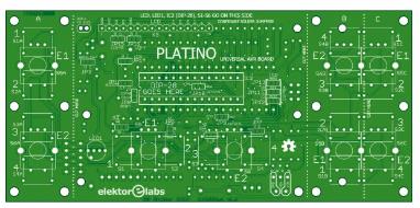
                           Platino, die Rückkehr

Bitte erfindet das Rad nicht neu!


Platino, die Rückkehr
Platino V1.4  elektor 150555-11   € 15,00
https://www.elektormagazine.de/files/magazine/2016/dolo/150555-PCB.pdf
https://www.elektor.de/search?q=150555


Damals, im Oktober 2011, präsentierten wir Platino, ein Projekt mit einer Platine in der Hauptrolle. Platino sollte es leichter machen, einen Mikrocontroller und Display, Knöpfe und Taster zu einem Projekt zusammenzufügen. Fast fünf Jahre später ist das Platino-Konzept immer noch aktuell, so dass wir uns entschlossen, die Platine gründlich zu überarbeiten.


Veröffentlicht in Heft 3/2016 auf Seite 50


www.elektor-magazine.de/100892
www.elektor-magazine.de/120094
www.elektor-magazine.de/150555
www.elektor-labs.com/platino
https://raw.githubusercontent.com/ElektorLabs/arduino/master/package_elektor-labs.com_ide-1.6.6_index.json
https://github.com/ElektorLabs/Arduino
https://github.com/ElektorLabs/150555-Platino/


Quelle:

https://www.elektormagazine.de/magazine/elektor-201603/28787


DIN A4  ausdrucken
********************************************************I*
Impressum: Fritz Prenninger, Haidestr. 11A, A-4600 Wels, Ober-Österreich, mailto:[email protected]
ENDE


Untergeordnete Seiten (2):LCD-AnzeigeMessgeräte