|
http://sites.schaltungen.at/arduino-uno-r4/uno-as-isp
Wels, am 2014-05-10BITTE nützen Sie doch rechts OBEN das Suchfeld [ ] [ Diese Site durchsuchen]DIN A3 oder DIN A4 quer ausdrucken ********************************************************************************** DIN A4 ausdrucken
*********************************************************
ARDUINO UNO as ISPInterfacing with Hardwarehttp://playground.arduino.cc/Main/InterfacingWithHardwareArduino as ISP (In-System Programmer)
Arduino als ISP (In-System-Programmer) Programmierung AVRs Brennen der Sanguino Bootloader zu ATmega 644p mit einem Arduino, lehrt Sie diesem Tutorial, wie man den Bootloader Sanguino zu einem ATmega 644p, die einen externen Resonator auf die Programmierschaltung hinzugefügt, bevor es keine Programmier akzeptieren muss brennen. Mit Arduino Uno als ISP, zeigt das Tutorial Schritt-für-Schritt (mit klaren Bildern), wie man eine ATtiny45/85 für die Programmierung mit dem Arduino Uno verdrahten. One exciting piece of hardware I received with my Digikey order was an Arduino Uno board (R3). There was conflicting information whether or not it could be used as an ISP (in-system programmer), so I decided to see for myself. It turned out that with just one tweak, I could use the $26 device to program my AVR chips, essentially eliminating the need for a separate ISP such as $22 USBtiny! This is obviously good news for any beginner with a budget, so I decided to write a short tutorial on how to do it. I used my USB password generator as a guinea pig for this project, so if you have wanted to try that out, this post also doubles as tutorial on how to build it on breadboard (good idea in any case before soldering it anywhere). Read on for details!
Mit Arduino UNO als ISP
Minimal circuit for AVR-powered USBFor this exact project, you’ll need the following components (of course you can also build something else, as long as the Arduino can power it):
If you’re really cheap, you could probably use just one pullup, wiring it to RESET while programming and then to D+ after you’re ready. Click the image for larger version, here’s the schematic if you need it. Update: As Ross McKenzie pointed out in the comments, 0.1 uF capacitor between VCC and GND should also be included. It seems to work without it most of the time, but it would be safer to have one there (to ensure the AVR chip being programmed gets a steady supply of power). Wiring the Uno for ProgrammingIf you haven’t flashed AVR chips before, it might be useful to know that the method used here is called serial programming with 6 pin interface. With dedicated ISP programmers you have the option to power the chip yourself (for example from external 3.3V source), but with Arduino as ISP, the safest bet is to power the chip from Arduino 5V and GND power connections. In addition to powering the chip, you should know where the MOSI, MISO and SCK pins are in your microcontroller of choice. You can find this information from very beginning of Atmel’s datasheets, along with rather clear instructions for how to power the chip (for ATtiny45/85 we only need VCC and GND but some ATmegas for example have multiple VCC/GND pins that need to be connected as well as the AVCC pin). Here’s the pinout of ATtiny45/85 for reference:
Here are the connections you need to make – note that because Arduino is already supplying 5V, I have detached the USB connector and used two jumper wires from the power rail to the breadboard rows 14 (VCC) and 17 (GND, behind the green wire). This is because the USB connector seemed to provide slightly higher voltage than the Arduino (about 0.1V more), and I thought it would be safest not to wire both at the same time, as current flowing from USB to Arduino circuit may not be such a good idea.
Programming
Once everything is wired up, you only need to upload the ArduinoISP sketch to your Arduino. If you’re running the 1.0 version of the Arduino IDE, there was some kind of timing/serial buffer/library mismatch and you need to tweak After flashing, your ‘duino should work as avrisp-compatible programmer for avrdude (and most likely also AVR Studio):
I’ve updated the USB password project zip to also contain a Makefile.uno that uses the Uno as a programmer. Furthermore, to help updating the fuses I added a new build target “fuse”. So once you’ve got everything wired up, just go to the directory and type the following commands to update fuses and flash the USB password firmware: make -f Makefile.uno flashmake -f Makefile.uno fuse That’s it! You are now equipped to flash any 8-bit AVR chip, anywhere, anytime (provided you carry your Arduino around, of course) with firmware of your choice. Where next + sponsor appreciationThanks for reading! I’d also like to remind all readers, that if you have a topic in mind you’d like me to cover, I’m taking suggestions via comments and e-mail (jokkebk at codeandlife.com). I’ll also take this opportunity to thank Martin, for the first donation supporting this blog. I really appreciate it! I already spent the donation on parts for project I’m hoping to cover here in the future. :) ********************************************************* http://arduino.cc/en/Tutorial/HomePage Arduino as ISP Programmer
ArduinoISP Turns your Arduino into an in-circuit programmer to re-program Atmega chips. Useful when you need to re-load the bootloader on an Arduino, if you're going from Arduino to an Atmega on a breadboard, or if you're making your own Arduino-compatible circuit on a breadboard.
Arduino als ISP Programmer
*********************************************************
http://arduino.cc/en/Tutorial/ArduinoToBreadboard Using an Arduino as an AVR ISP (In-System Programmer)This tutorial explains how to use an Arduino board as an AVR ISP (in-system programmer). This allows you to use the board to burn the bootloader onto an AVR (e.g. the ATmega168 or ATmega328 used in Arduino). The code in this example is based on the mega-isp firmware by Randall Bohn. InstructionsTo use your Arduino board to burn a bootloader onto an AVR, you need to follow a few simple steps.
Circuit (targeting Arduino Uno, Duemilanove, or Diecimila)An Arduino board serving as an ISP to program the ATmega on another Arduino board. On the Arduino Uno, you'll need to connect a 10 uF capacitor between reset and ground (after uploading the ArduinoISP sketch). Note that you need access to the reset pin on the target board, which isn't available on NG or older boards.
Circuit (targeting Arduino NG or older)On NG or older boards, connect the reset wire to pin 1 of the Atmega chip on the board, as shown above.
Circuit (targeting an AVR on a breadboard)
See the Arduino to Breadboard tutorial for details. ShareUsing an Arduino board to program an ATmega. Because no external clock source is connected, the ATmega must be configured to use its internal clock. Using an Arduino board to program an ATmega, with external crystal and associated capacitors (18 or 22 picofarads
*********************************************************
http://arduino.cc/en/Tutorial/ArduinoToBreadboard From Arduino to a Microcontroller on a BreadboardThis tutorial explains how to migrate from an Arduino board to a standalone microcontroller on a breadboard. It's similar to this tutorial, but uses an Arduino board to program the ATmega on the breadboard. Unless you choose to use the minimal configuration described at the end of this tutorial, you'll need four components (besides the Arduino, ATmega328, and breadboard):
Note that these techniques only work with the Arduino Duemilanove w/ an ATmega328, not the Arduino Uno (or older Arduino boards w/ an ATmega168).
Uploading Using an Arduino Board
Once your ATmega328p has the Arduino bootloader on it, you can upload programs to it using the USB-to-serial convertor (FTDI chip) on an Arduino board. To do, you remove the microcontroller from the Arduino board so the FTDI chip can talk to the microcontroller on the breadboard instead. The diagram at right shows how to connect the RX and TX lines from the Arduino board to the ATmega on the breadboard. To program the microcontroller, select "Arduino Duemilanove or Nano w/ ATmega328" from the the Tools > Board menu (or "ATmega328 on a breadboard (8 MHz internal clock)" if you're using the minimal configuration described below). Then upload as usual. Uploading sketches to an ATmega on a breadboard. Remember to remove the microcontroller from the Arduino board!
Minimal Circuit (Eliminating the External Clock)If you don't have the extra 16 MHz crystal and 18-22 picofarad capacitors used in the above examples, you can configure the ATmega328 to use its internal 8 MHz RC oscillator as a clock source instead. (You don't really need the 10K pullup resistor on the reset pin either, so we remove it to get a truly minimal configuration.) You'll need to install support for an additional hardware configuration:
Once you've done this, you can burn the bootloader and upload programs onto your ATmega328 as described above. Be sure to select "ATmega328 on a breadboard (8 MHz internal clock)" when burning the bootloader. (If you select the wrong item and configure the microcontroller to use an external clock, it won't work unless you connect one.)  Using an Arduino board to burn the bootloader onto an ATmega on a breadboard (w/o an external clock)
Getting Rid of the Arduino Board
Once you've programmed the ATmega on the breadboard, you can eliminate the Arduino. To do so, you'll need to provide an alternative power supply for the microcontroller. See the standalone Arduino on a breadboard tutorial for details.
********************************************************* Building an Arduino on a Breadboardhttp://arduino.cc/en/Main/Standalone OverviewThis tutorial shows you how to build an Arduino compatible breadboard with an Atmel Atmega8/168/328 AVR microcontroller and FTDI FT232 breakout board from SparkFun. You could also use the Arduino USB Mini.
Originally created David A. Mellis Parts
To do this, you'll need:
The Supplies Basic Parts for wiring up Arduino
USB to Serial Communication BoardYou will need a FT232 USB Breakout board from SparkFun. There are two options available from them: If you plan to use the top option and have not yet soldered headers to the breakout board, now would be a good time. Bootloading your Atmega ChipsThere are several options for bootloading your Atmega chips, a few of which are covered in this tutorial. If you wish to bootload your Atmega chips using your breadboard, an additional part will make your life much easier but is not necessary. AVR Programming Adapter from Sparkfun, SKU BOB-08508
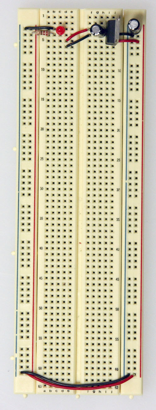
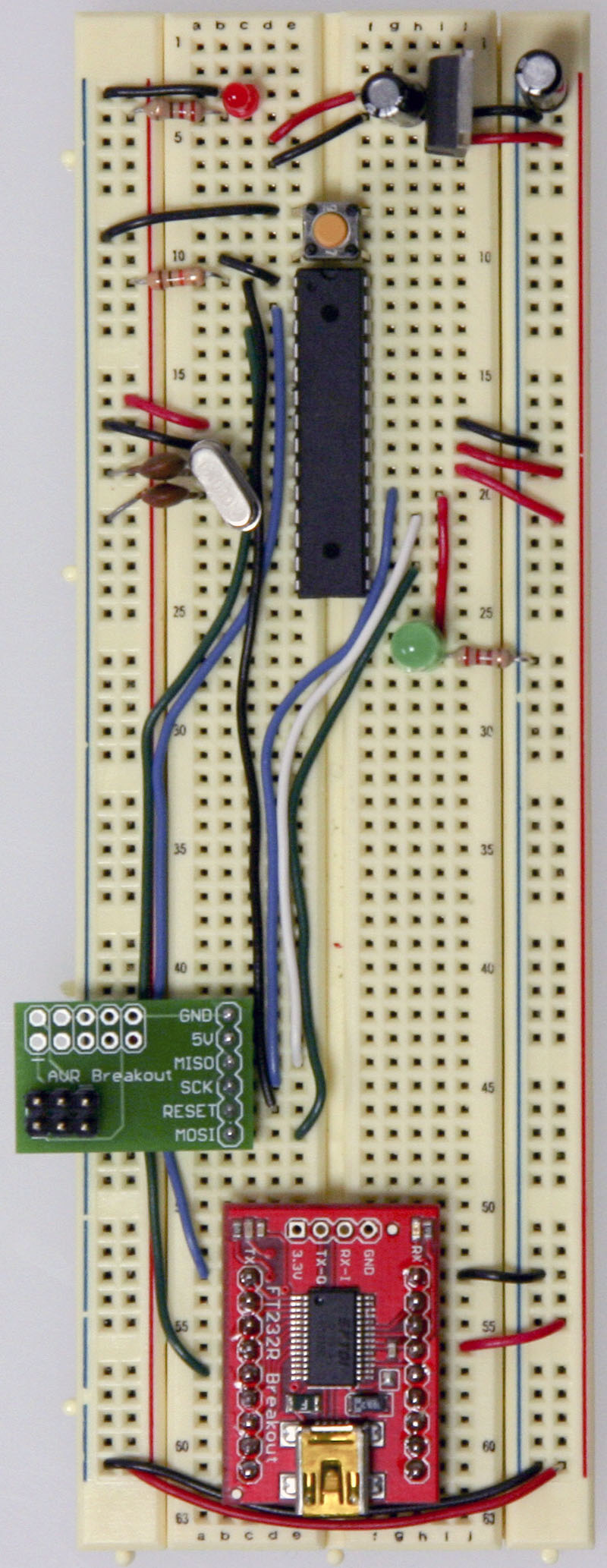
Adding circuitry for a power supplyIf you've already worked with microcontrollers, it is likely that you already have a preferred way to wire up a power supply to your board, so go ahead and do it that way. In case you need some reminders, here are some pictures of one way to go about it. (This version uses a 5V regulated power supply)
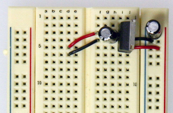
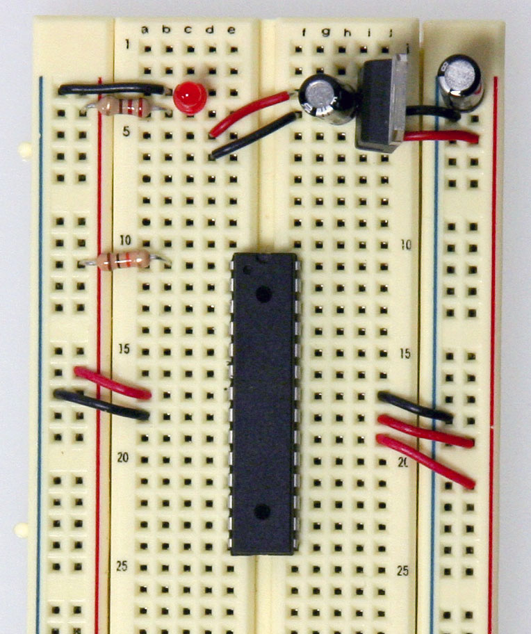
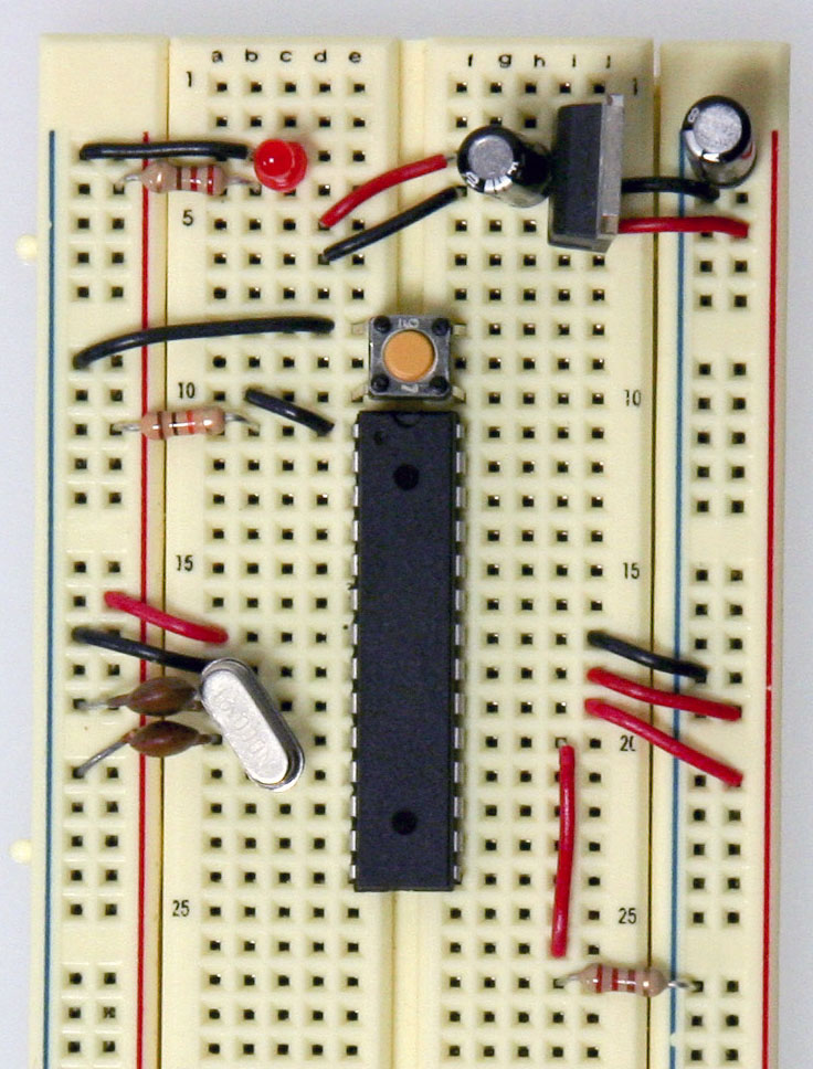
Add power and ground wires for where your voltage regulator will be.
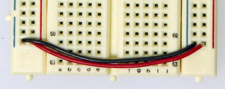
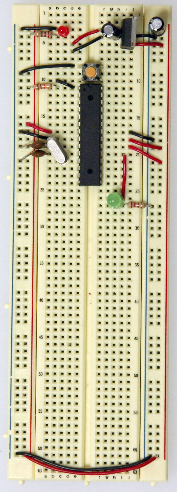
Add power and ground wires at the bottom of your board connecting each rail. Add the 7805 power regulator and the lines to power the board. The regulator is a TO-220 package where the Input from the external power supply goes input on the left, ground is in the middle and the 5V output is on the right (when facing the front of the regulator). Add power OUT and ground wires that connect to the right and left rails of the breadboard. Also, add a 10uF capacitor between the IN of the regulator and the ground as well as a 10uF capacitor on the right rail between power and ground. The silver strip on the capacitor signifies the ground leg.
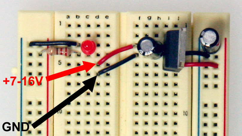
Add an LED and a 220-ohm resistor on the left side of your board across from the voltage regulator. An LED attached to power like this is a great troubleshooting trick. You'll always know when your board is being powered as well as quickly know if your board is being shorted.
The red and black wires to the left of the voltage regulator is where your power supply will be plugged in. The red wire is for the POWER and the black wire is for the GROUND. Be sure to only attach a power supply that is between 7-16V. Any lower and you won't get 5V out of your regulator. Any higher and your regulator may be damaged. A 9V battery, 9V DC power supply, or 12V DC power supply is suitable. Now that the power-basics are done you are ready to load on the chip!
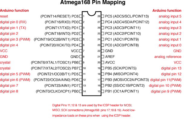
ATMEGA8/168/328 BasicsBefore moving on, check out this image. It's a great resource for learning what each of the pins on your Atmega chip do in relation to the Arduino's functions. This will clarify a lot of confusion behind why you hook up certain pins the way you do. For even more detailed information, take a peek at the datasheet for the Atmega 168 (short version) (long version). Here's the sheet for the atmega328 (short version) (long version)
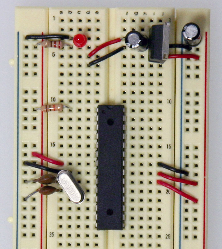
Start by connecting a 10k ohm pullup resistor to +5V from the RESET pin in order to prevent the chip from resetting itself during normal operation. The RESET pin reboots the chip when pulled down to ground. In later steps we will show you how to add a reset switch that takes advantage of this.
Add a 16 MHz external clock between pin 9 and 10, and add two 22 pF capacitors running to ground from each of those pins.
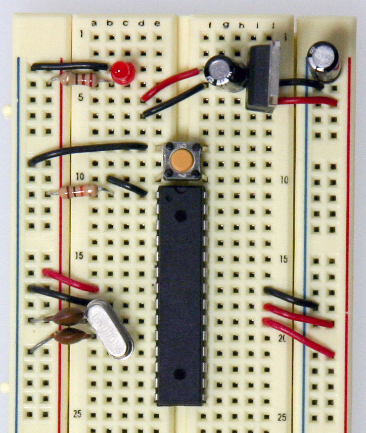
Add the small tactile switch so that you can reset the Arduino whenever we'd like and prepare the chip for uploading a new program. A quick momentary press of this switch will reset the chip when needed. Add the switch just above the top of the Atmega chip crossing the gap in the breadboard. Then, add a wire from the bottom left leg of the switch to the RESET pin of the Atmega chip and a wire from the top left leg of the switch to ground.
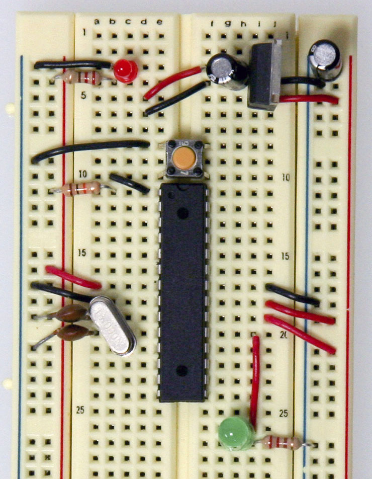
The chip used on this board is actually already programmed using the blink_led program that comes with the Arduino software. If you already have an Arduino printed circuit board running, it is a good idea to go ahead and check the breadboard version you are building with a chip you know works. Pull the chip from your working Arduino and try it on this board. The blink_led program blinks pin 13. Pin 13 on the Arduino is NOT the AVR ATMEGA8-16PU/ATMEGA168-16PU pin 13. It is actually pin 19 on the Atmega chip. Refer to the pin mapping above to be sure you are plugging it in correctly.
Finally, add the LED. The long leg or the anode connects to the red wire and the short leg or the cathode connects to the 220 ohm resistor going to ground.
At this point if you had already programmed your chip somewhere else and didn't need this breadboard circuit to reprogram the chip, you could stop here. But part of the fun is in-circuit programming so keep going to really make a full USB-Arduino-circuit on a breadboard!
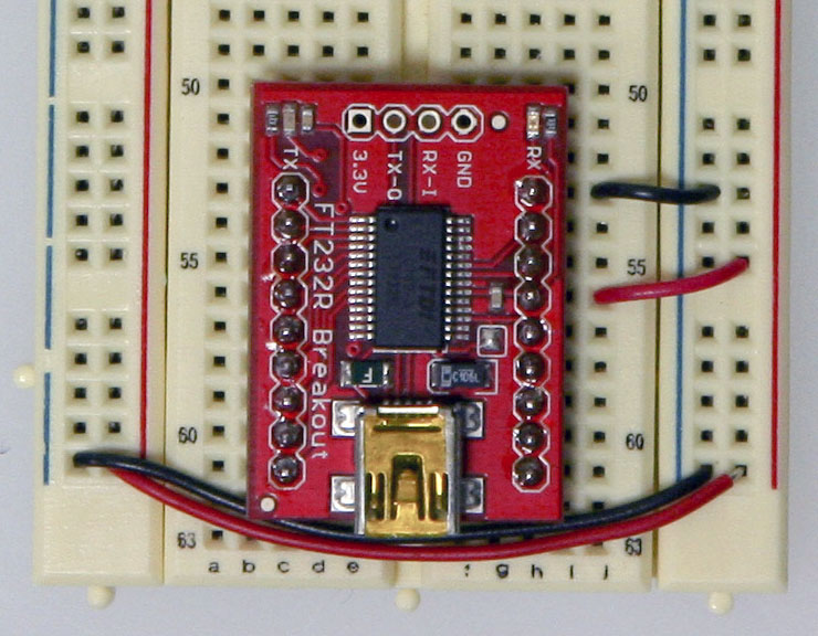
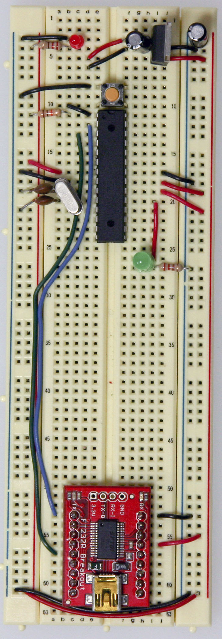
Arduino-ReadyNow we'll be adding the USB to Serial breakout board to our Arduino breadboard circuit. If you haven't added male headers to your breakout board, you will need to do it now. Connect the VCCIO of the breakout board to power and the GND to ground.
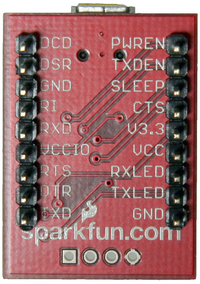
Curious what all the pin outs are for the SparkFun FT232 breakout board, just simply flip it over! In this situation we'll be using VCC (to supply 5V from the USB port to your board), GND, TXD, and RXD.
Now, it's time to get the USB to serial breakout board talking with your new Arduino setup. Connect the RX (pin 2) of your Atmega chip to the TX of the USB to serial board, and connect the TX (pin 3) of your Atmega chip to the RX of the USB to serial board.
And there you have it... ready to be plugged in, powered up and programmed! But wait, there's another step right? If you pulled your Atmega chip out of your Arduino, it has most likely been programed several times by yourself and so it definitely has been bootloaded, so you won't need to move any further in this tutorial. However, if you purchased some extra Atmega8 or Atmega168 chips from an online store they will have NOT been bootloaded with the Arduino bootloader (with the exception of Adafruit Industries). What does this mean? You won't be able to program your chips using the USB to serial breakout board and the Arduino software. So, in order to make your new chips useful for Arduino you MUST bootload them and MUST check out step 4.
Other Breadboard Options
The uDuino Setup by Tymn Twillman
Boarduino by Ladyada
Bootloading your chips OPTIONALBootloading OptionsThere are two options for bootloading your chips. The first being quite easy and the other being a little more tricky. We will cover both.
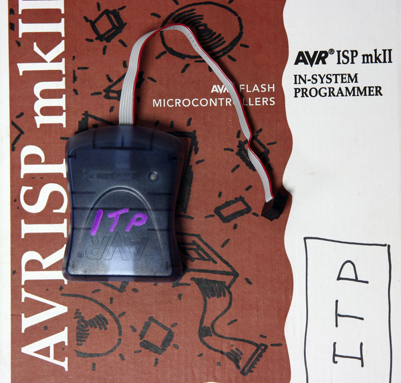
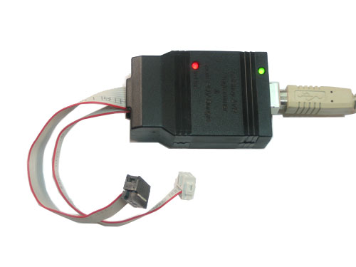
There are also many different kinds of AVR programmers but two are most commonly used:
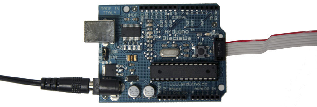
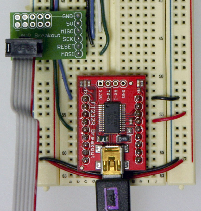
The AVRISP mkII can be purchased from Digikey (Part # ATAVRISP2-ND) while the USBtinyISP must be assembled and can be found at Adafruit Industries. Using an Arduino boardPlace your Atmega chip into the Arduino board with the divot of the chip facing outward. Set the jumper to an external power supply and connect a 12V power brick (your board needs to be externally powered when using the AVR ISP mkII but is not needed with the AVRtinyISP) . Then, attach the 6-pin female plug of your AVR programmer to the 6 male header ICSP pins with the plastic nub of the ribbon cable head facing inward. NOTE: The AVR ISP mkII turns its LED green when they've been hooked up correctly and are ready for programming. The LED turns red if it is hooked up wrong.
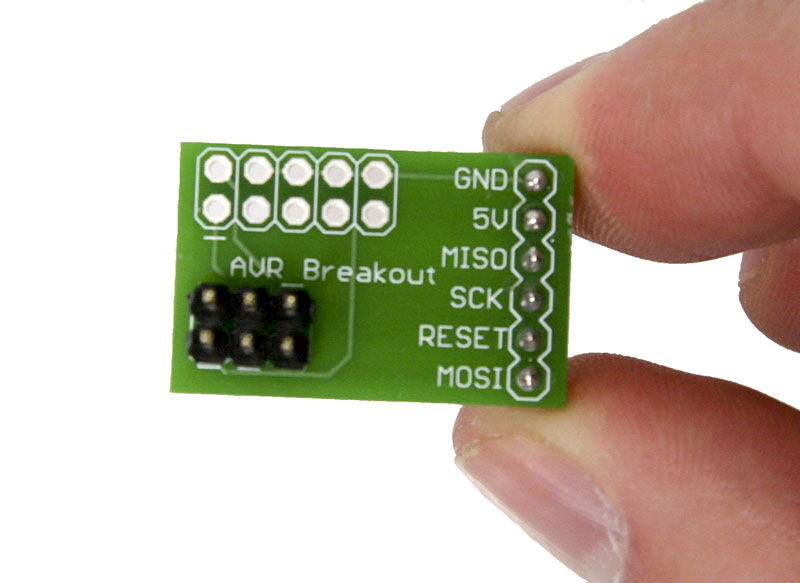
Using your breadboardWhen bootloading an Atmega chip on a breadboard, the AVR programming adapter (SKU BOB-08508) from Sparkfun is incredibly handy. This adapter breaks out the 6 pins from the programmer to 6 inline pins for easy attachment to the breadboard. All the pins are also labeled making it very easy to connect it up to your chip.
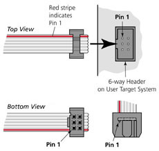
Don't worry, if you don't have an AVR programming adapter you can still bootload without it. It will however be more of a headache to set up. The two images to the left are great references when hooking up a programmer to an Atmega chip without an adapter board. The images will tell you what all the holes in the 6-pin AVR plug are and you will simply need to stick wires in the end and run them to your Atmega chip.
This image is a view from the bottom and labels each of the holes. Take note of the square as to what orientation your cable is in.
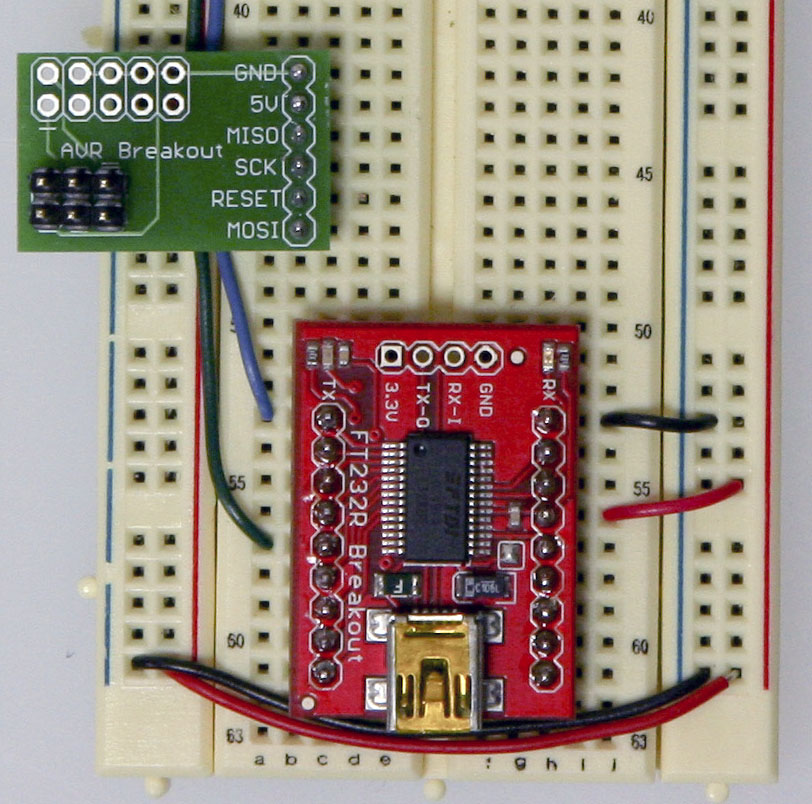
Let's begin! With the breadboard you prepared above, add two wires for power and ground for your AVR programmer.
Now plug the AVR programming adapter into the breadboard with the GND pin matching up with the ground wire you just ran and the 5V pin matching up with the power wire you just ran.
In this step you will need to add the last four wires needed by the AVR programmer for proper bootloading. Be sure to refer to the Arduino pin mapping for help wiring this up.
Almost there! Just plug in a USB cable to your USB breakout board and plug the 6-pin plug of your AVR programmer to your AVR programming adapter. The black nub of the 6-pin head must be facing upwards towards the Atmega chip. In the next step, we'll show you have to use the Arduino software to burn your bootloader!
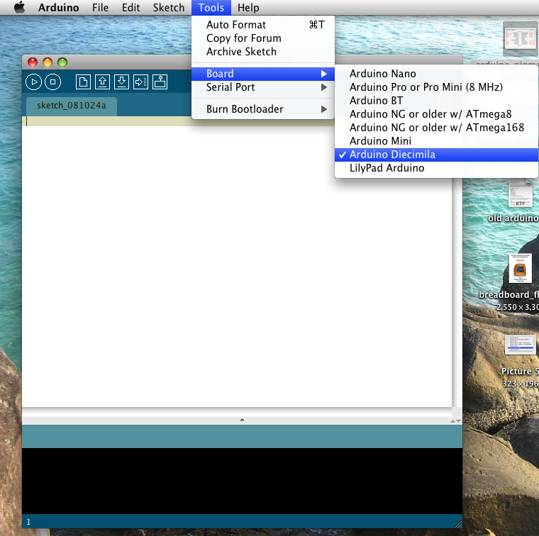
Time to burn!Fire up Arduino and then go to 'Tools' and 'Board'. Choosing the type of board you'd like to use will effect which bootloader you will be put on your chip. Most commonly you will be using the Diecimilia or the most recent version of Arduino for an Atmega PDIP, however if you'd like to bootload an Arduino Lilypad, Arduino Mini, Arduino Nano, or any of the older Arduino versions, choose the appropriate board.
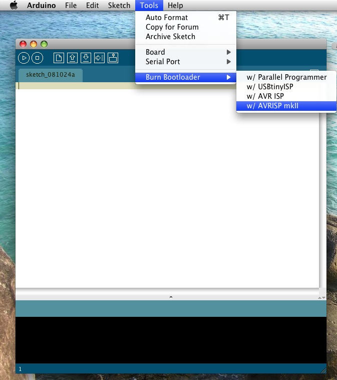
Then, go to 'Tools' and 'Burn Bootloader' and choose the programmer you will be using.
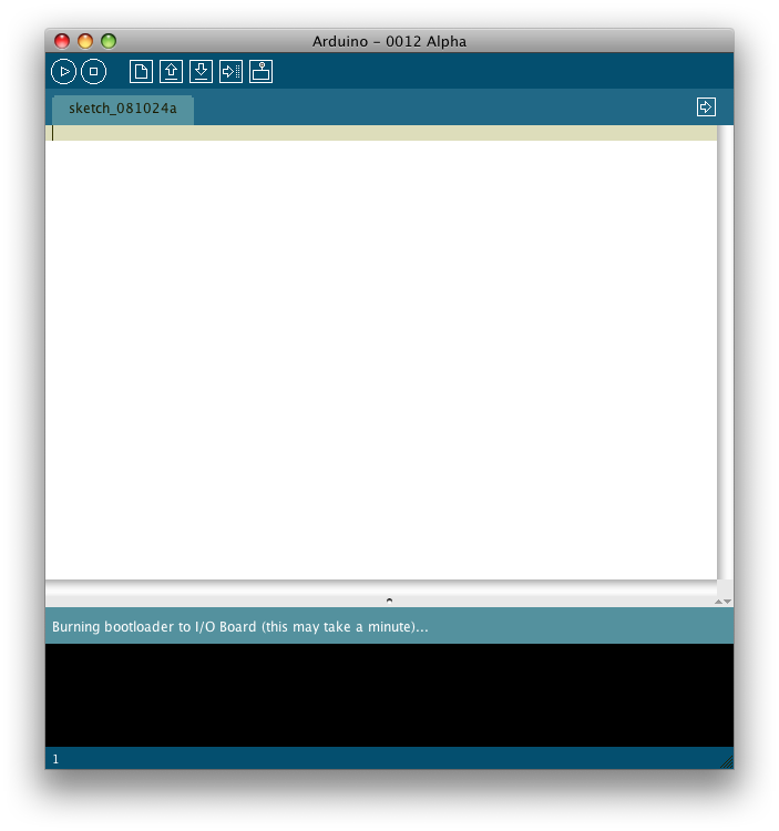
Once you chose your programmer, the AVR programmer will begin bootloading your Atmega chip and a message will appear in the status bar which reads "Burning bootloader to I/O Board (this may take a minute)..." Lights will flicker on your programmer.
When done bootloading, the status bar will be updated with the message "Done burning bootloader." Your chip is now ready to be programmer using the Arduino software! Congrats! Power cycle your Arduino and your new Atmega chip will be running a simple LED blink program with pin 13 (if this is not the case, try programming it with one). If this is working, it was most definitely a success. NOTE: On occasion, the process of bootloading an Atmega chip with the AVR ISP mkII will take an extraordinarily long period of time. Usually it should only take a couple minutes and in fact, the AVRtinyISP finishes much quicker. However, there are times where after 5-10 minutes it still appears to be bootloading. I found this to be an odd hiccup (perhaps it is triple checking the data flow) and after giving it ample time, 10 minutes or so, I usually unplug the programmer only to find the burning process to be a success and has ended long ago. I by no means endorse this method and you take all responsibility in whatever may happen to your chip, but in my experience it has been fairly harmless though you should proceed with caution. It is very possible that you may damage your chip in the process.
Quelle: http://arduino.cc/en/Main/Standalone
|


