|
http://sites.schaltungen.at/arduino-uno-r4/1-0-5-r2
Wels, am 2014-05-10BITTE nützen Sie doch rechts OBEN das Suchfeld [ ] [ Diese Site durchsuchen]DIN A3 oder DIN A4 quer ausdrucken ********************************************************************************** DIN A4 ausdrucken
*********************************************************
ARDUINO-Programm-Version STAND 2012
Arduino 1.0.5-r2 ist die neueste Arduino 1.0 Release Candidate 2 (RC2)
Bisher Release 001
Endungen von *.ino in *.pde ändern um den Sketch in eine Pre-1.0-IDE laden zu können. Baumstrukturen sind zwar gut zum Programmieren. Wenn man sich einen ersten schnellen Überblick verschaffen möchte ist eine Excel-Liste besser. Ich habe mir die Arbeit gemacht eine solche über alle ARDUINO-Sketche zu erstellen wie ich dies vor 30 Jahren auch immer tat. Nach dekadischem Nummernsystem / dekadische Gliederung. http://de.wikipedia.org/wiki/Nummerung Deutsche Übersetzungen einiger Arduino Tutorials sind hier zu finden: http://playground.arduino.cc/Deutsch/HomePage ********************************************************* ARDUINO > Learning > Examples http://arduino.cc/en/Tutorial/HomePage Entwicklungsumgebung ARDUINO UNO R3 Programmiersprache "Processing" Sketch'es
MENU > Datei > Beispiele
01.Basics 02.Digital 03.Analog 04.Communication 05.Control 06.Sensors 07.Display 08.Strings 09.USB 4 10.StarterkKit 11.ArduinoISP 12.EEPROM 13.Esplora 14.Ethernet 15.Firmata 16.GSM 17.LiquidCrystal 18.Robot_Control 19. Robot_Motor 20.SD 21.Servo 22.SoftwareSerial 23.SPI 24.Stepper 25.TFT 26.WiFi 27.Wire
Diese Tabelle ist auch mit den dabei verwendeten Elektronik-Bauteilen vorhanden,
Wurde in akribischer Kleinarbeit mit viel Zeitaufwabd erstellt, daher nur downloadbar unter
www.schaltungen.at
704_d_ARDUINO-x_1.0.5-r2 – MENU - Datei - Beispiele_2a.xls
*********************************************************
Ich persönlich finde ja die Videos im Internet unsinnig.
Eine Schaltung versteht man nur wenn man auch einen Schaltplan lesen kann.
Farbige Kabel in Bread-Bords gesteckt geht schnell aber die Schaltungsfunktion ist kein bisschen verstädnlich.
Ferner ist zu bemerken diese Anfängerschaltungen mit meist nur 3 Bauteilen kann man auch fliegend am ARDUINO stecken.
Beim Programm schreibe passiert es mir immer mal wieder das ich keine geschweiften Klammern setze.
Bei schlechten Kopien schauen diese aus wie runde Klammern.
Und überall steht 9600 Baud das BOARD und der USB-PORT kann aber heute 115200 Baud, daher verwende ich diese Geschwindigkeit.
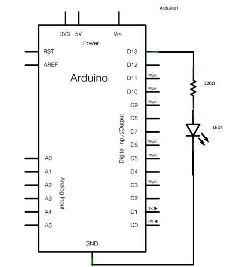
Auf D13 (SCK) ist eine LED schon eingebaut daher wird extern keine LED benötigt,
sollte aber eine LED PWM angesteuert werden geht dies nur am pin D3 D5 D6 D9 D10 D11
Andere Darstellungsart mit zusätzlicher Pin-Bezeichnung D13 (SCK) aber D13 ist immer D13 und da hängt auch die eingebaute LED uber einen OpAmp daran.

/*
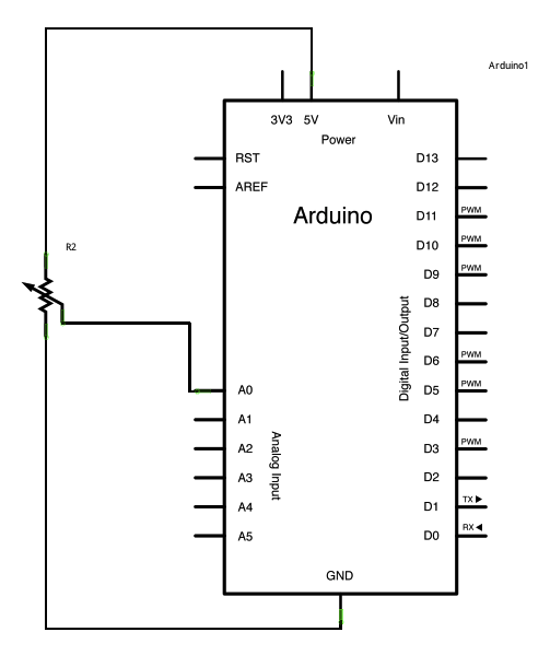
AnalogReadSerial Reads an analog input on pin 0, prints the result to the serial monitor. Attach the center pin of a potentiometer to pin A0, and the outside pins to +5V and ground. */ // the setup routine runs once when you press reset: void setup() { // initialize serial communication at 115200 bits per second: Serial.begin(115200); } // the loop routine runs over and over again forever: void loop() { // read the input on analog pin 0: int sensorValue = analogRead(A0); // print out the value you read: Serial.println(sensorValue); delay(1); // delay in between reads for stability }
void setup() {
// put your setup code here, to run once: } void loop() { // put your main code here, to run repeatedly: }
/*
Blink Turns on an LED on for one second, then off for one second, repeatedly. */ // Pin 13 has an LED connected on most Arduino boards. // give it a name: int led = 13; // the setup routine runs once when you press reset: void setup() { // initialize the digital pin as an output. pinMode(led, OUTPUT); } // the loop routine runs over and over again forever: void loop() { digitalWrite(led, HIGH); // turn the LED on (HIGH is the voltage level) delay(1000); // wait for a second digitalWrite(led, LOW); // turn the LED off by making the voltage LOW delay(1000); // wait for a second }
/*
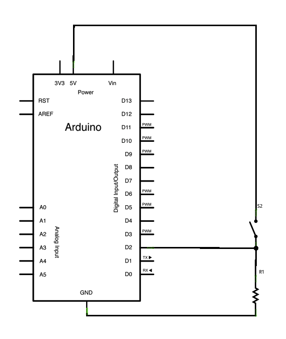
DigitalReadSerial Reads a digital input on pin 2, prints the result to the serial monitor */ // digital pin 2 has a pushbutton attached to it. Give it a name: int pushButton = 2; // the setup routine runs once when you press reset: void setup() { // initialize serial communication at 9600 bits per second: Serial.begin(115200); // make the pushbutton's pin an input: pinMode(pushButton, INPUT); } // the loop routine runs over and over again forever: void loop() { // read the input pin: int buttonState = digitalRead(pushButton); // print out the state of the button: Serial.println(buttonState); delay(1); // delay in between reads for stability }
/*
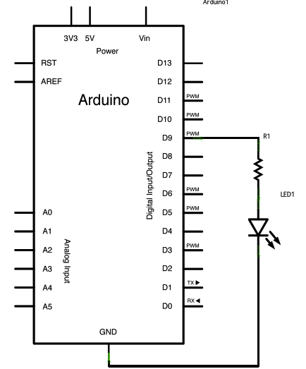
Fade This example shows how to fade an LED on pin 9 using the analogWrite() function. */ int led = 9; // the pin that the LED is attached to int brightness = 0; // how bright the LED is int fadeAmount = 5; // how many points to fade the LED by // the setup routine runs once when you press reset: void setup() { // declare pin 9 to be an output: pinMode(led, OUTPUT); } // the loop routine runs over and over again forever: void loop() { // set the brightness of pin 9: analogWrite(led, brightness); // change the brightness for next time through the loop: brightness = brightness + fadeAmount; // reverse the direction of the fading at the ends of the fade: if (brightness == 0 || brightness == 255) { fadeAmount = -fadeAmount ; } // wait for 30 milliseconds to see the dimming effect delay(30); }

/*
ReadAnalogVoltage Reads an analog input on pin 0, converts it to voltage, and prints the result to the serial monitor. Attach the center pin of a potentiometer to pin A0, and the outside pins to +5V and ground. */ // the setup routine runs once when you press reset: void setup() { // initialize serial communication at 115200 bits per second: Serial.begin(115200); } // the loop routine runs over and over again forever: void loop() { // read the input on analog pin 0: int sensorValue = analogRead(A0); // Convert the analog reading (which goes from 0 - 1023) to a voltage (0 - 5V): float voltage = sensorValue * (5.0 / 1023.0); // print out the value you read: Serial.println(voltage); } ********************************************************* 2.Digital

/* Blink without Delay
Turns on and off a light emitting diode(LED) connected to a digital pin, without using the delay() function. This means that other code can run at the same time without being interrupted by the LED code. The circuit: * LED attached from pin 13 to ground. * Note: on most Arduinos, there is already an LED on the board that's attached to pin 13, so no hardware is needed for this example. http://www.arduino.cc/en/Tutorial/BlinkWithoutDelay */ // constants won't change. Used here to // set pin numbers: const int ledPin = 13; // the number of the LED pin // Variables will change: int ledState = LOW; // ledState used to set the LED long previousMillis = 0; // will store last time LED was updated // the follow variables is a long because the time, measured in miliseconds, // will quickly become a bigger number than can be stored in an int. long interval = 1000; // interval at which to blink (milliseconds) void setup() { // set the digital pin as output: pinMode(ledPin, OUTPUT); } void loop() { // here is where you'd put code that needs to be running all the time. // check to see if it's time to blink the LED; that is, if the // difference between the current time and last time you blinked // the LED is bigger than the interval at which you want to // blink the LED. unsigned long currentMillis = millis(); if(currentMillis - previousMillis > interval) { // save the last time you blinked the LED previousMillis = currentMillis; // if the LED is off turn it on and vice-versa: if (ledState == LOW) ledState = HIGH; else ledState = LOW; // set the LED with the ledState of the variable: digitalWrite(ledPin, ledState); } }
/*
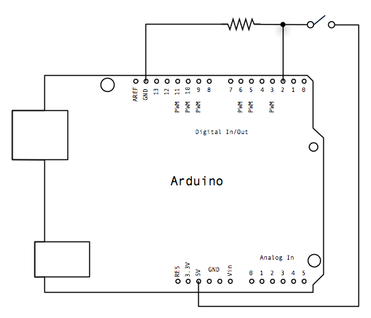
Button Turns on and off a light emitting diode(LED) connected to digital pin 13, when pressing a pushbutton attached to pin 2. The circuit: * LED attached from pin 13 to ground * pushbutton attached to pin 2 from +5V * 10K resistor attached to pin 2 from ground * Note: on most Arduinos there is already an LED on the board attached to pin 13. .http://www.arduino.cc/en/Tutorial/Button */ // constants won't change. They're used here to // set pin numbers: const int buttonPin = 2; // the number of the pushbutton pin const int ledPin = 13; // the number of the LED pin // variables will change: int buttonState = 0; // variable for reading the pushbutton status void setup() { // initialize the LED pin as an output: pinMode(ledPin, OUTPUT); // initialize the pushbutton pin as an input: pinMode(buttonPin, INPUT); } void loop(){ // read the state of the pushbutton value: buttonState = digitalRead(buttonPin); // check if the pushbutton is pressed. // if it is, the buttonState is HIGH: if (buttonState == HIGH) { // turn LED on: digitalWrite(ledPin, HIGH); } else { // turn LED off: digitalWrite(ledPin, LOW); } }

/*
Debounce Each time the input pin goes from LOW to HIGH (e.g. because of a push-button press), the output pin is toggled from LOW to HIGH or HIGH to LOW. There's a minimum delay between toggles to debounce the circuit (i.e. to ignore noise). The circuit: * LED attached from pin 13 to ground * pushbutton attached from pin 2 to +5V * 10K resistor attached from pin 2 to ground * Note: On most Arduino boards, there is already an LED on the board connected to pin 13, so you don't need any extra components for this example. http://www.arduino.cc/en/Tutorial/Debounce */ // constants won't change. They're used here to // set pin numbers: const int buttonPin = 2; // the number of the pushbutton pin const int ledPin = 13; // the number of the LED pin // Variables will change: int ledState = HIGH; // the current state of the output pin int buttonState; // the current reading from the input pin int lastButtonState = LOW; // the previous reading from the input pin // the following variables are long's because the time, measured in miliseconds, // will quickly become a bigger number than can be stored in an int. long lastDebounceTime = 0; // the last time the output pin was toggled long debounceDelay = 50; // the debounce time; increase if the output flickers void setup() { pinMode(buttonPin, INPUT); pinMode(ledPin, OUTPUT); // set initial LED state digitalWrite(ledPin, ledState); } void loop() { // read the state of the switch into a local variable: int reading = digitalRead(buttonPin); // check to see if you just pressed the button // (i.e. the input went from LOW to HIGH), and you've waited // long enough since the last press to ignore any noise: // If the switch changed, due to noise or pressing: if (reading != lastButtonState) { // reset the debouncing timer lastDebounceTime = millis(); } if ((millis() - lastDebounceTime) > debounceDelay) { // whatever the reading is at, it's been there for longer // than the debounce delay, so take it as the actual current state: // if the button state has changed: if (reading != buttonState) { buttonState = reading; // only toggle the LED if the new button state is HIGH if (buttonState == HIGH) { ledState = !ledState; } } } // set the LED: digitalWrite(ledPin, ledState); // save the reading. Next time through the loop, // it'll be the lastButtonState: lastButtonState = reading; } Button State Change: 
/*
State change detection (edge detection) Often, you don't need to know the state of a digital input all the time, but you just need to know when the input changes from one state to another. For example, you want to know when a button goes from OFF to ON. This is called state change detection, or edge detection. This example shows how to detect when a button or button changes from off to on and on to off. The circuit: * pushbutton attached to pin 2 from +5V * 10K resistor attached to pin 2 from ground * LED attached from pin 13 to ground (or use the built-in LED on most Arduino boards) http://arduino.cc/en/Tutorial/ButtonStateChange */ // this constant won't change: const int buttonPin = 2; // the pin that the pushbutton is attached to const int ledPin = 13; // the pin that the LED is attached to // Variables will change: int buttonPushCounter = 0; // counter for the number of button presses int buttonState = 0; // current state of the button int lastButtonState = 0; // previous state of the button void setup() { // initialize the button pin as a input: pinMode(buttonPin, INPUT); // initialize the LED as an output: pinMode(ledPin, OUTPUT); // initialize serial communication: Serial.begin(115200); } void loop() { // read the pushbutton input pin: buttonState = digitalRead(buttonPin); // compare the buttonState to its previous state if (buttonState != lastButtonState) { // if the state has changed, increment the counter if (buttonState == HIGH) { // if the current state is HIGH then the button // wend from off to on: buttonPushCounter++; Serial.println("on"); Serial.print("number of button pushes: "); Serial.println(buttonPushCounter); } else { // if the current state is LOW then the button // wend from on to off: Serial.println("off"); } } // save the current state as the last state, //for next time through the loop lastButtonState = buttonState; // turns on the LED every four button pushes by // checking the modulo of the button push counter. // the modulo function gives you the remainder of // the division of two numbers: if (buttonPushCounter % 4 == 0) { digitalWrite(ledPin, HIGH); } else { digitalWrite(ledPin, LOW); } } Input PullUp Serial: 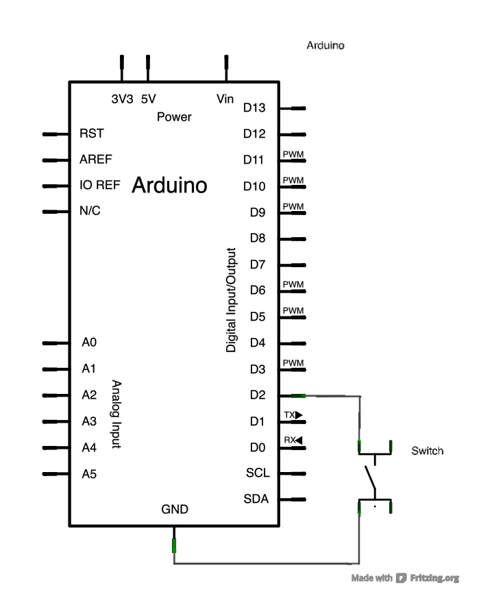
/*
Input Pullup Serial This example demonstrates the use of pinMode(INPUT_PULLUP). It reads a digital input on pin 2 and prints the results to the serial monitor. The circuit: * Momentary switch attached from pin 2 to ground * Built-in LED on pin 13 Unlike pinMode(INPUT), there is no pull-down resistor necessary. An internal 20k Ohm resistor is pulled to 5V. This configuration causes the input to read HIGH when the switch is open, and LOW when it is closed. http://www.arduino.cc/en/Tutorial/InputPullupSerial */ void setup(){ //start serial connection Serial.begin(115200); //configure pin2 as an input and enable the internal pull-up resistor pinMode(2, INPUT_PULLUP); pinMode(13, OUTPUT); } void loop(){ //read the pushbutton value into a variable int sensorVal = digitalRead(2); //print out the value of the pushbutton Serial.println(sensorVal); // Keep in mind the pullup means the pushbutton's // logic is inverted. It goes HIGH when it's open, // and LOW when it's pressed. Turn on pin 13 when the // button's pressed, and off when it's not: if (sensorVal == HIGH) { digitalWrite(13, LOW); } else { digitalWrite(13, HIGH); } } Tone: 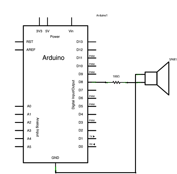
/*
Melody Plays a melody circuit: * 8-ohm speaker on digital pin 8 http://arduino.cc/en/Tutorial/Tone */ #include "pitches.h" // notes in the melody: int melody[] = { NOTE_C4, NOTE_G3,NOTE_G3, NOTE_A3, NOTE_G3,0, NOTE_B3, NOTE_C4}; // note durations: 4 = quarter note, 8 = eighth note, etc.: int noteDurations[] = { 4, 8, 8, 4,4,4,4,4 }; void setup() { // iterate over the notes of the melody: for (int thisNote = 0; thisNote < 8; thisNote++) { // to calculate the note duration, take one second // divided by the note type. //e.g. quarter note = 1000 / 4, eighth note = 1000/8, etc. int noteDuration = 1000/noteDurations[thisNote]; tone(8, melody[thisNote],noteDuration); // to distinguish the notes, set a minimum time between them. // the note's duration + 30% seems to work well: int pauseBetweenNotes = noteDuration * 1.30; delay(pauseBetweenNotes); // stop the tone playing: noTone(8); } } void loop() { // no need to repeat the melody. } Pitch follower: 
/*
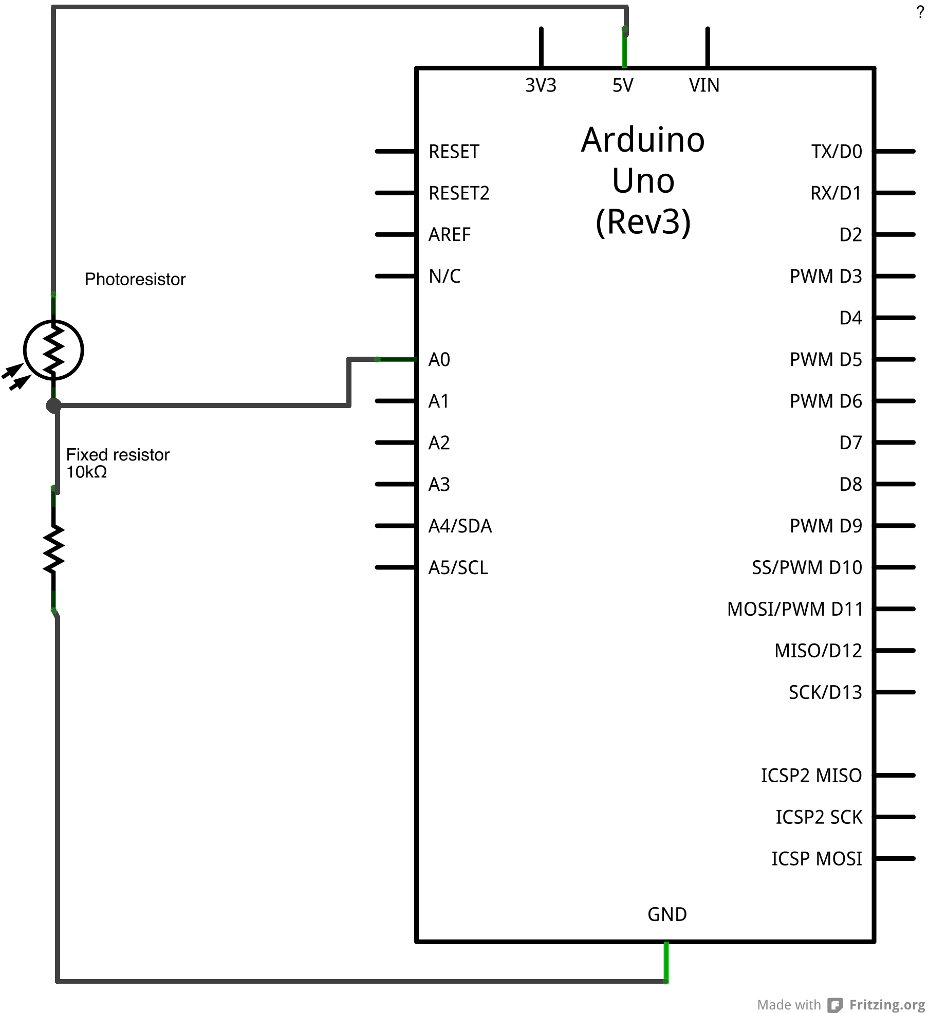
Pitch follower Plays a pitch that changes based on a changing analog input circuit: * 8-ohm speaker on digital pin 9 * photoresistor on analog 0 to 5V * 4.7K resistor on analog 0 to ground http://arduino.cc/en/Tutorial/Tone2 */ void setup() { // initialize serial communications (for debugging only): Serial.begin(115200); } void loop() { // read the sensor: int sensorReading = analogRead(A0); // print the sensor reading so you know its range Serial.println(sensorReading); // map the analog input range (in this case, 400 - 1000 from the photoresistor) // to the output pitch range (120 - 1500Hz) // change the minimum and maximum input numbers below // depending on the range your sensor's giving: int thisPitch = map(sensorReading, 400, 1000, 120, 1500); // play the pitch: tone(9, thisPitch, 10); delay(1); // delay in between reads for stability } Simple Keyboard: 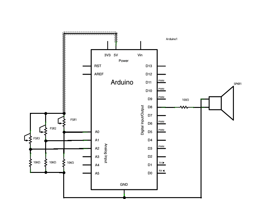
/*
keyboard Plays a pitch that changes based on a changing analog input circuit: * 3 force-sensing resistors from +5V to analog in 0 through 5 * 3 10K resistors from analog in 0 through 5 to ground * 8-ohm speaker on digital pin 8 http://arduino.cc/en/Tutorial/Tone3 */ #include "pitches.h" const int threshold = 10; // minimum reading of the sensors that generates a note // notes to play, corresponding to the 3 sensors: int notes[] = { NOTE_A4, NOTE_B4,NOTE_C3 }; void setup() { } void loop() { for (int thisSensor = 0; thisSensor < 3; thisSensor++) { // get a sensor reading: int sensorReading = analogRead(thisSensor); // if the sensor is pressed hard enough: if (sensorReading > threshold) { // play the note corresponding to this sensor: tone(8, notes[thisSensor], 20); } } }
/*************************************************
* Public Constants *************************************************/ #define NOTE_B0 31 #define NOTE_C1 33 #define NOTE_CS1 35 #define NOTE_D1 37 #define NOTE_DS1 39 #define NOTE_E1 41 #define NOTE_F1 44 #define NOTE_FS1 46 #define NOTE_G1 49 #define NOTE_GS1 52 #define NOTE_A1 55 #define NOTE_AS1 58 #define NOTE_B1 62 #define NOTE_C2 65 #define NOTE_CS2 69 #define NOTE_D2 73 #define NOTE_DS2 78 #define NOTE_E2 82 #define NOTE_F2 87 #define NOTE_FS2 93 #define NOTE_G2 98 #define NOTE_GS2 104 #define NOTE_A2 110 #define NOTE_AS2 117 #define NOTE_B2 123 #define NOTE_C3 131 #define NOTE_CS3 139 #define NOTE_D3 147 #define NOTE_DS3 156 #define NOTE_E3 165 #define NOTE_F3 175 #define NOTE_FS3 185 #define NOTE_G3 196 #define NOTE_GS3 208 #define NOTE_A3 220 #define NOTE_AS3 233 #define NOTE_B3 247 #define NOTE_C4 262 #define NOTE_CS4 277 #define NOTE_D4 294 #define NOTE_DS4 311 #define NOTE_E4 330 #define NOTE_F4 349 #define NOTE_FS4 370 #define NOTE_G4 392 #define NOTE_GS4 415 #define NOTE_A4 440 #define NOTE_AS4 466 #define NOTE_B4 494 #define NOTE_C5 523 #define NOTE_CS5 554 #define NOTE_D5 587 #define NOTE_DS5 622 #define NOTE_E5 659 #define NOTE_F5 698 #define NOTE_FS5 740 #define NOTE_G5 784 #define NOTE_GS5 831 #define NOTE_A5 880 #define NOTE_AS5 932 #define NOTE_B5 988 #define NOTE_C6 1047 #define NOTE_CS6 1109 #define NOTE_D6 1175 #define NOTE_DS6 1245 #define NOTE_E6 1319 #define NOTE_F6 1397 #define NOTE_FS6 1480 #define NOTE_G6 1568 #define NOTE_GS6 1661 #define NOTE_A6 1760 #define NOTE_AS6 1865 #define NOTE_B6 1976 #define NOTE_C7 2093 #define NOTE_CS7 2217 #define NOTE_D7 2349 #define NOTE_DS7 2489 #define NOTE_E7 2637 #define NOTE_F7 2794 #define NOTE_FS7 2960 #define NOTE_G7 3136 #define NOTE_GS7 3322 #define NOTE_A7 3520 #define NOTE_AS7 3729 #define NOTE_B7 3951 #define NOTE_C8 4186 #define NOTE_CS8 4435 #define NOTE_D8 4699 #define NOTE_DS8 4978 Tone4: 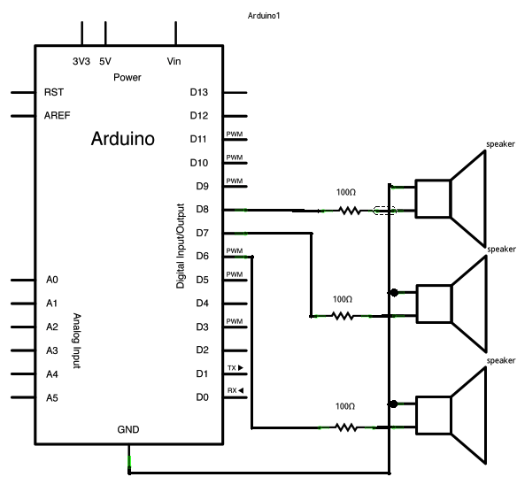
/*
Multiple tone player Plays multiple tones on multiple pins in sequence circuit: * 3 8-ohm speaker on digital pins 6, 7, and 8 http://arduino.cc/en/Tutorial/Tone4 */ void setup() { } void loop() { // turn off tone function for pin 8: noTone(8); // play a note on pin 6 for 200 ms: tone(6, 440, 200); delay(200); // turn off tone function for pin 6: noTone(6); // play a note on pin 7 for 500 ms: tone(7, 494, 500); delay(500); // turn off tone function for pin 7: noTone(7); // play a note on pin 8 for 500 ms: tone(8, 523, 300); delay(300); } ********************************************************* Weitere Beispiele habe ich mir erspart da ohnehin alles mehrmals im Internet zu finden ist. Jeder kupfert wie ich auch, von jemanden ab, macht dabei Fehler und schon geht nichts mehr. Ein Grundlagen Buch und sich selbst etwas einlesen damit man auch seine Fehler suchen und finden kann, wird notwendig sein. Ohne Fleiß kein Preis DIN A4 ausdrucken
*********************************************************
Impressum: Fritz Prenninger, Haidestr. 11A, A-4600 Wels, Ober-Österreich, mailto:[email protected] ENDE |
